Correction device and method for airborne two-dimensional active phased array radar antenna

A phased array radar and phased array antenna technology, applied in radio wave measurement systems, instruments, etc., can solve the problems of antenna performance degradation, impact on combat use, and antenna sidelobe beam pointing accuracy, reducing the number of correction iterations. , Improve the effect of calibration efficiency

Active Publication Date: 2019-06-18
CHINA ELECTRONIC TECH GRP CORP NO 38 RES INST
View PDF8 Cites 10 Cited by
  • Summary
  • Abstract
  • Description
  • Claims
  • Application Information

AI Technical Summary

Problems solved by technology

The performance of the antenna is degraded due to the mechanical and thermal deformation of the front surface, and the active microwave devices such as delay amplifier components and TR components are caused by factors such as changes in the working environment, aging of long-term working devices, or performance differences between components after replacement. Changes in the amplitude and phase of the excitation signal of the antenna radiation array element cause the decrease in the antenna sidelobe and beam pointing accuracy, which leads to a decrease in the detection ability and detection accuracy of the SAR / MTI radar for monitoring targets, affecting combat use

Method used


Image

  • Correction device and method for airborne two-dimensional active phased array radar antenna
  • Correction device and method for airborne two-dimensional active phased array radar antenna
  • Correction device and method for airborne two-dimensional active phased array radar antenna

Examples


Embodiment Construction

[0050] The embodiments of the present invention are described in detail below. This embodiment is implemented on the premise of the technical solution of the present invention, and detailed implementation methods and specific operating procedures are provided, but the protection scope of the present invention is not limited to the following implementation example.

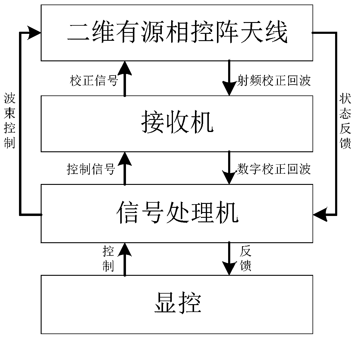
[0051] Such as figure 1 As shown, it is a frame diagram of the two-dimensional active phased array SAR / MTI radar system of the present invention. The SAR / MTI radar system mainly includes a two-dimensional active phased array antenna, a receiver, a processor, a display and control unit, combined figure 2 Antenna calibration transmit / receive branch signal flow chart for further explanation:

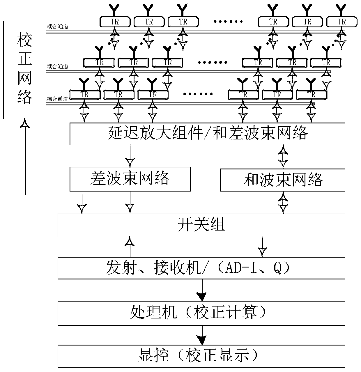
[0052] Such as figure 2 As shown, the two-dimensional active phased array antenna mainly consists of TR components, coupling channels, correction networks, delay amplification components / sum and difference beam networks, dif...


PUM


Abstract

The invention discloses a correction device and method for an airborne two-dimensional active phased array radar antenna. The correction device comprises a two-dimensional active phased array antenna,a receiver, a signal processor and a display control unit. According to the correction device and method of the invention, the amplitude and phase error of the TR channels of a complex two-dimensional active phased array antenna is realized on the basis of the hardware architecture of the radar with no additional hardware resources required; an automatic correction function is adopted, so that the efficiency of the calibration of an airborne SAR/MTI radar with a large number of TR channels is greatly improved; an efficient correction algorithm is adopted, the number of correction iterations is reduced, correction accuracy is improved, and system calibration reliability is increased; detailed functional division is performed on each link of correction, and quantifiable indicator requirements are provided for each function module, and therefore, the test and verification of the correction device and method in engineering practice and the application of the correction device and method to the engineering practice can be benefitted; and the reliable operating performance of the active phased array radar is improved. The correction device and method can adapt to the rapid development trend of modern battlefield reconnaissance and surveillance equipment so as to meet the application requirements of SAR/MTI radars for ground/sea multi-mode and multi-mode integrated reconnaissance andsurveillance.

Description

technical field [0001] The invention relates to the field of airborne radar technology, in particular to an airborne two-dimensional active phased array radar antenna calibration device and method. Background technique [0002] With the rapid development of modern battlefield reconnaissance and surveillance equipment, SAR / MTI radars should meet the needs of ground / sea comprehensive reconnaissance and surveillance. Tracking and other working modes, and can flexibly configure the number of channels in various modes. The flexibility of the traditional mechanical scanning antenna system cannot meet the real-time requirements of modern combat, while the two-dimensional active phased array antenna is covered with T / R components in the radiation unit, the aperture radiation efficiency is higher, the radiation power is greater, and the two-dimensional direction The beam scanning on the radar is more flexible, and the two-dimensional active phased array antenna system is an inevitab...

Claims


Application Information

Patent Timeline
Patent Type & Authority Applications(China)
IPC IPC(8): G01S7/40
Inventor 陈凯孙龙王磊江凯
Owner CHINA ELECTRONIC TECH GRP CORP NO 38 RES INST
Why Eureka
Try Eureka