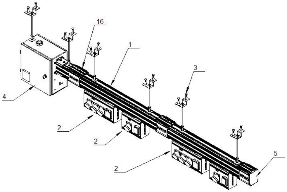
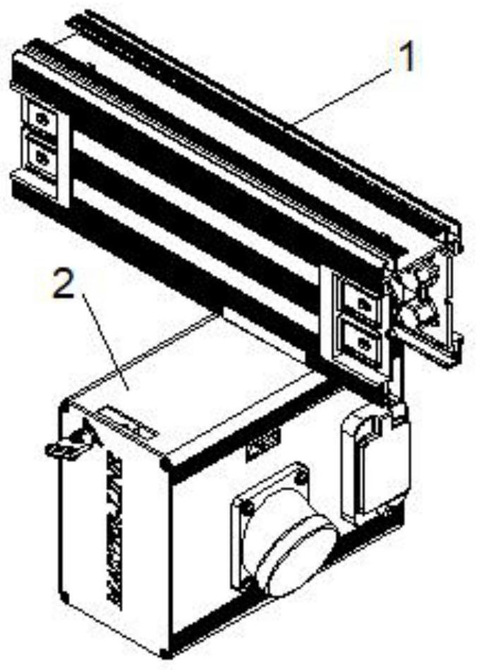
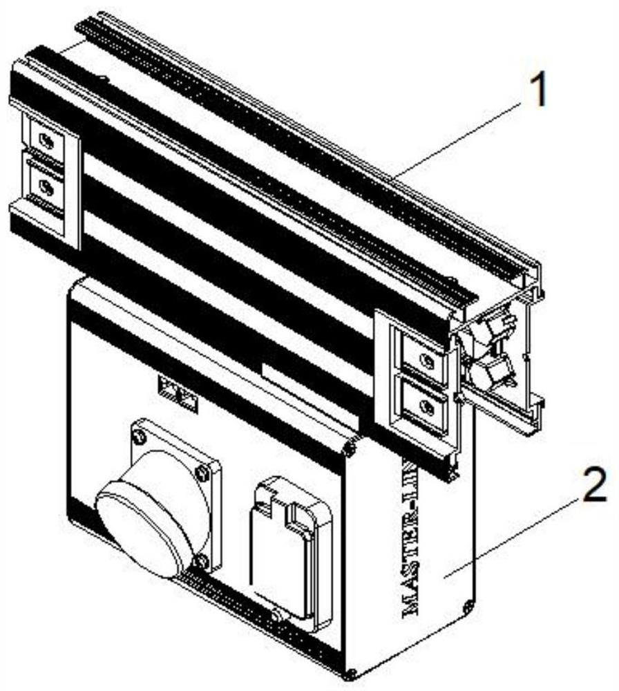
The busway connection of two straight sections can be connected to the busway at both ends by the busway tap unit, or the fixed connection can be realized by the connection mechanism. The connection mechanism usually includes the shell, the
busbar protection part, the
busbar connector, Shell connection structure, in the prior art, there are many technical defects in each component: (1) The
busbar and the busway shell are mostly connected by direct plug connection, the heat dissipation performance of the busbar is poor, and the safety performance is low
(2) There are many lines in the
data center, and the communication lines need to be arranged with the help of the busway housing. In the prior art, the communication lines are laid on the side wall of the housing, and a cover plate is required to fix the communication lines. The installation is complicated and the wiring inconvenient
(3) The installation of the busway bottom gusset and the busway shell is usually connected by riveting, bolts and nuts. The installation and
connection form is complicated and inconvenient to disassemble
(4) The busbar protection parts at the end of the busway in the existing
data center are injection molded parts, with
copper nuts embedded in them, which are used to connect the connecting row and the busbar. When using a large torque to fasten the busbar and the protective part, The embedded
copper nut will be pulled out of the surface of the injection molded part, damaging the structure and affecting safe use; at the same time, the
copper nut embedded in the injection molded part will cause cumbersome production process and increase the cost of the part
(5) After the existing protective part is assembled with the busbar shell, the protective part and the shell cannot be completely fitted, and there is a gap between the two, which affects the appearance and reduces the electrical creepage distance, affecting the insulation performance of the protective connection
(6) The connection method of the connector is complicated and the installation is inconvenient
(7) The connection structure of the shell usually adopts the connection between the connecting plate and the busway shell through multiple fasteners. The connection method of the busway at both ends is simple, and the connection strength is low. When vibration occurs, the connection is easy to be directly damaged. Housing, low safety; (8) The connection structure of the housing requires multiple fastening bolts to connect between the connecting plate and the shell, and between the connecting plate and the connecting plate, which is inconvenient to install and low in installation efficiency
The steps of the entire rear plate
processing and the number of
stamping dies required are relatively large, resulting in a complicated production process and requiring more man-hours
(3) The fixing plate used to fix the micro-break support frame and the monitoring module support frame in the existing plug-in box adopts two L-shaped plates arranged outwards, and then the support frame is fastened by 4 screws, and at the same time It is also necessary to
drill holes and tap on the fixing plate, the process is complicated, and the fixing effect is not stable
(4) The existing micro-break support frame adopts an integrated U-shaped plate, and its size has requirements for the knife edge of the bending
machine. If the distance is too short, a small knife edge is required
(5) In the existing monitoring module, the main board and the CT integrated board are installed on different brackets, so when fixing the monitoring module, two brackets need to be used for fixing, which will consume manpower and time during
assembly(7) Moreover, due to the limited volume of the plug-in plastic parts, the gap between the electrical terminals on both sides of the plug-in plastic parts is small, which is easy to cause short-circuit accidents and has potential safety hazards
(8) The
locking mechanism on the side plate cannot fix the rotary
handle when locked, which is likely to cause misoperation and cause the plug-in box to fall

