

Surgical navigation system of mandibular angle osteotomy
A technology of surgical navigation and osteotomy, which is applied in the field of surgical navigation, can solve the problems of no advantage in postoperative effect and improvement of patient satisfaction, limit the application range of surgical navigation system, and high difficulty of fixing the marking module, so as to shorten the operation time, The effect of reducing surgical complications and avoiding touching dangerous areas
- Summary
- Abstract
- Description
- Claims
- Application Information
AI Technical Summary
Problems solved by technology
Method used
Image

Examples
Embodiment Construction
[0031] The present invention will be described in further detail below in conjunction with the accompanying drawings.
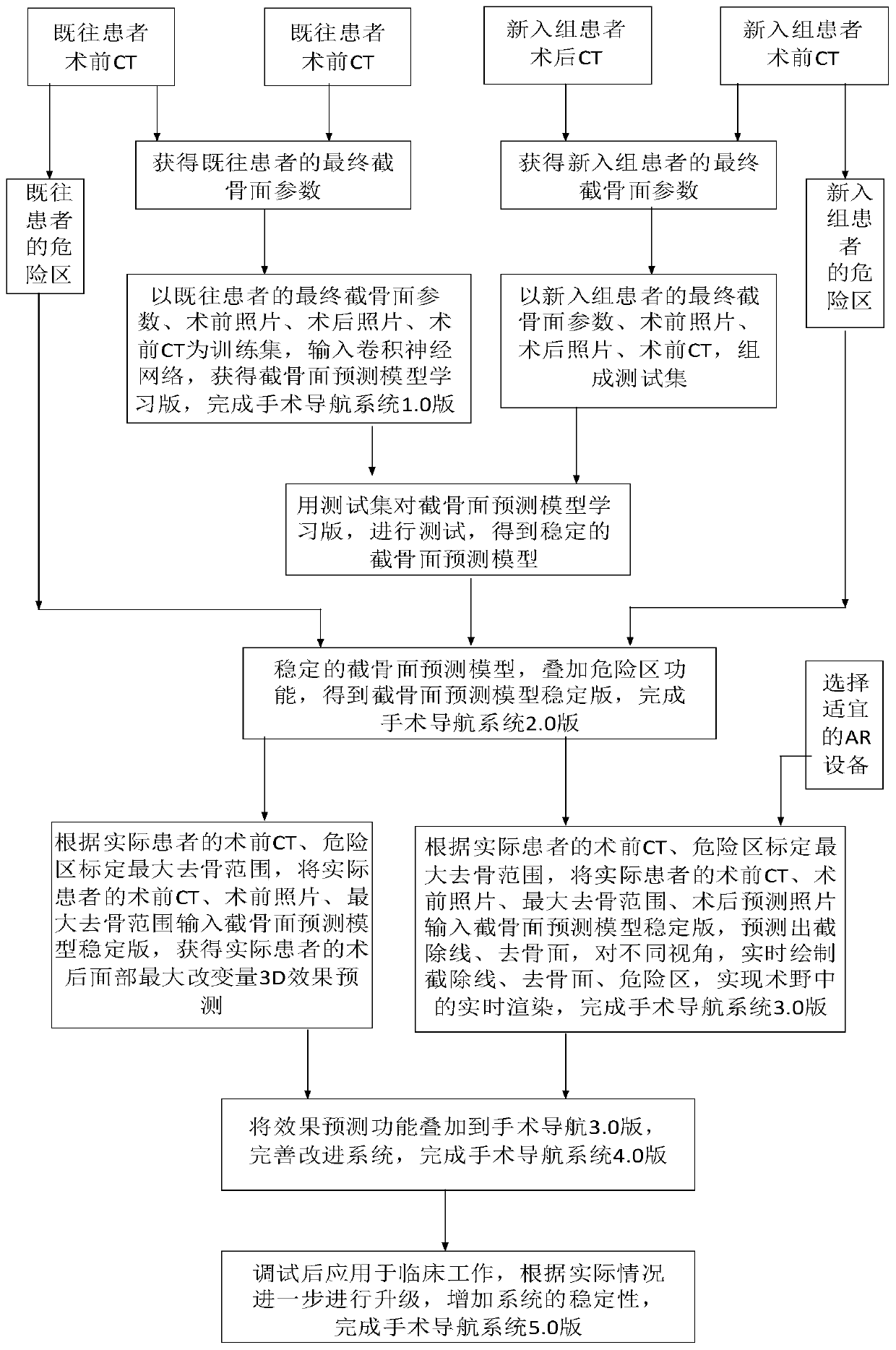
[0032] figure 1 It is the general structure diagram of the surgical navigation system.
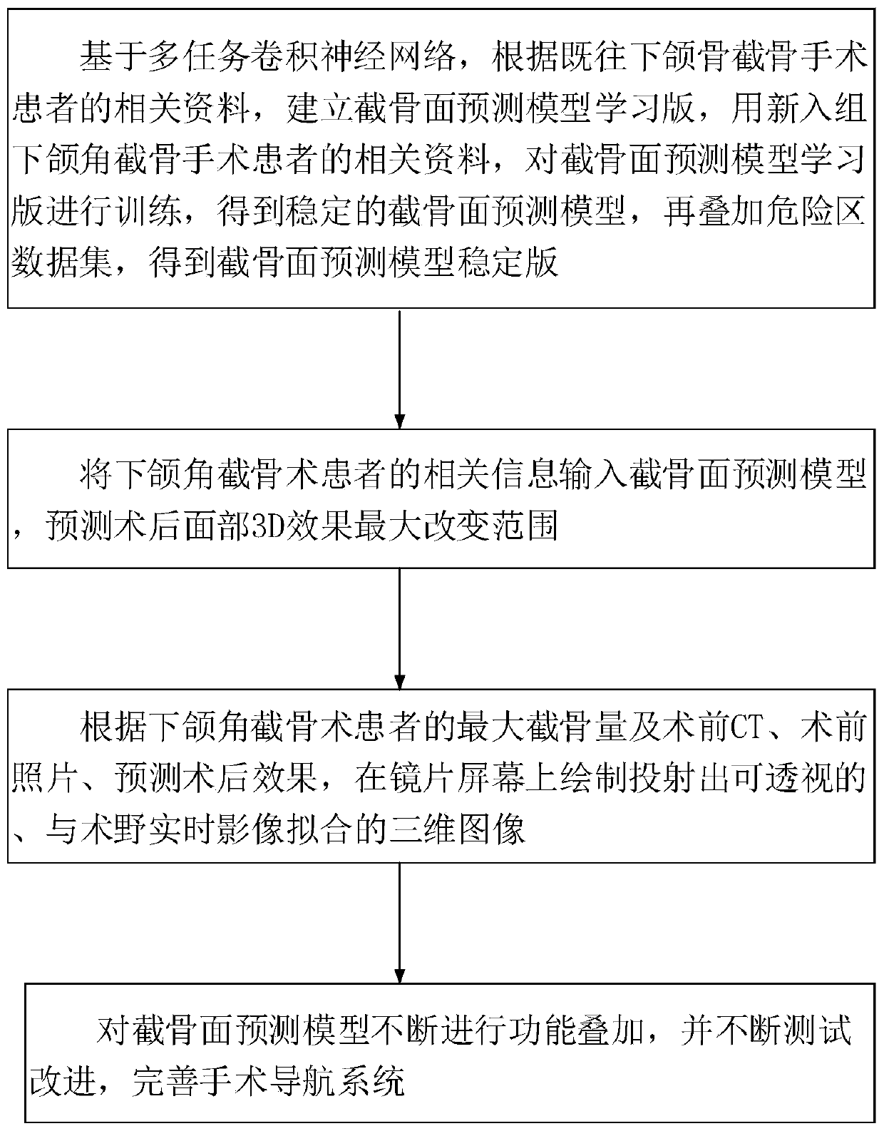
[0033] Specifically, a surgical navigation system for mandibular angle osteotomy, such as figure 2 shown, including the following steps:
[0034] S1. Based on the relevant data of patients with previous mandibular angle osteotomy, establish a study version of the osteotomy surface prediction model, use the relevant data of newly enrolled patients with mandibular angle osteotomy to test the learning version of the osteotomy surface prediction model, and obtain a stable Osteotomy surface prediction model;
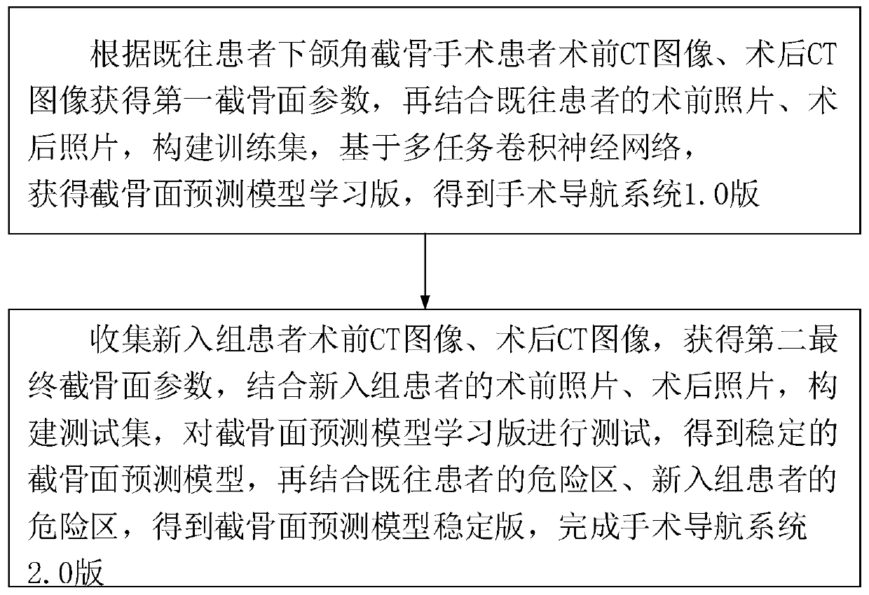
[0035] Specifically, such as image 3 shown, including the following steps:
[0036] A1. According to the preoperative CT images and postoperative CT images of patients with mandibular angle osteotomy in previous patients, the parameters of the first osteotomy surf...
PUM
 Abstract
Description
Claims
Application Information