Sand-stone separator

A technology of sand and gravel separator and sand separator, which is applied in solid separation, wet separation, filter and screen, etc., which can solve problems such as non-compliance with environmental protection requirements, blockage of urban sewer pipes, interference with the direction of travel of mixer trucks and forklifts, etc. Achieve the effects of saving civil engineering costs and floor space, reducing the height of the main engine, and reducing the probability of material blocking

Pending Publication Date: 2019-06-21
ZHEJIANG SINOU ENVIRONMENTAL PROTECTION EQUIP CO LTD
View PDF0 Cites 0 Cited by
  • Summary
  • Abstract
  • Description
  • Claims
  • Application Information

AI Technical Summary

Problems solved by technology

On a general construction site, there is only a car washing site and a slurry tank with a certain volume. The above-mentioned equipment is cleaned anywhere, and the sand, stone and slurry are not separated. A large amount of agglomerated waste piles up like a mountain, causing a lot of waste of sand and gravel resources
[0005] At present, the waste concrete in domestic mixing plants is mainly cleaned by sand and gravel cleaners and then separated and recycled by sand and gravel separators, which is very troublesome.
In addition, the existing sand and gravel separator needs to be fed through the guide trough, and the base site of the waste concrete recovery system must also be equipped with a long slope platform to assist the feeding of the concrete truck, which occupies a large area and greatly improves the overall efficiency of the waste concrete recovery system. The layout brings great trouble, even if it is barely arranged, it will cause great interference to the walking direction of mixer trucks, forklifts, etc.

Method used


Image

  • Sand-stone separator
  • Sand-stone separator

Examples


Embodiment Construction

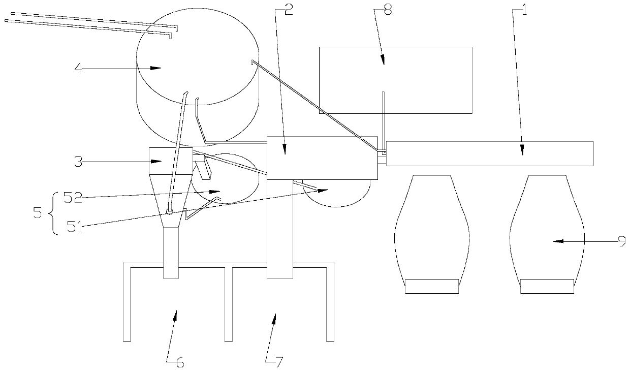
[0021] refer to figure 1 , a kind of sand and gravel separator of the present invention, comprises guide tank 1, trommel 2, spiral sand divider 3, stirring tank 4, conical pool 5, sand stockyard 6, stone stockyard 7 and pool 8, described The material guide tank 1 is connected with the pool 8 and the trommel 2 respectively through pipelines, and the conical pool 5 includes a first mud pool 51 and a second mud pool 52, and the first mud pool 51 and the second mud pool 52 are respectively It is located under the trommel 2 and the spiral sand separator 3 and is respectively connected to the trommel 2 and the spiral sand separator 3 through pipelines. The rock outlet of the trommel 2 and the sand outlet of the spiral sand separator 3 are respectively provided Leading to the conveyor belt of the stone stockyard 7 and the sand stockyard 6, the mixing tank 4 is connected with the spiral sand separator 3 through a pipeline, the trough 1 is provided with a flushing pump and a flushing n...


PUM


Abstract

The invention discloses a sand-stone separator. The sand-stone separator comprises a material guide groove, a drum sieve, a spiral sand separator, a stirring tank, a conical pool, a sand pile yard, astone pile yard and a water pool, wherein the material guide groove is connected with the water pool and the drum sieve through a pipeline separately; the conical pool comprises a first mud pool and asecond mud pool; the first mud pool and the second mud pool are located below the drum sieve and the spiral sand separator, and connected with the drum sieve and the spiral sand separator through a pipeline separately; a conveying belt connected to the stone pile yard and the sand pile yard are arranged at a stone outlet port of the drum sieve and a sand outlet port of the spiral sand separator separately; and the stirring tank is connected with the spiral sand separator through a pipeline. The height of a main machine is reduced by detaching a traditional sand-stone separator into the drum sieve for separating stone and the spiral sand separator for separating sand, so that the problem that inconvenience is brought to reversing of a concrete vehicle by a reversing slope table is solved,no reversing slope is really realized, and the civil engineering cost and the floor area are saved.

Description

[0001] 【Technical field】 [0002] The invention relates to the technical field of mechanical equipment for building construction, in particular to the technical field of a sand and gravel separator. [0003] 【Background technique】 [0004] Concrete is a synonym for concrete. With the vigorous development of my country's construction industry, concrete is widely used in various buildings. Equipment such as concrete mixer trucks, concrete mixing stations and concrete mixing buildings need to be cleaned and maintained after a day's work. On a general construction site, there is only a car washing site and a slurry tank with a certain volume. The above-mentioned equipment is cleaned anywhere, and the sand, stone and slurry are not separated. A large amount of agglomerated waste piles up like a mountain, causing a lot of waste of sand and gravel resources. [0005] At present, the waste concrete in domestic mixing plants is mainly cleaned by sand and gravel cleaners and then separ...

Claims


Application Information

Patent Timeline
Patent Type & Authority Applications(China)
IPC IPC(8): B03B7/00B03B5/52B07B1/22
Inventor 万安铭戴申平
Owner ZHEJIANG SINOU ENVIRONMENTAL PROTECTION EQUIP CO LTD
Why Eureka
Try Eureka