
Device and method for measuring microscopic topography of workpiece surface coated with cutting fluid

A microscopic topography and workpiece surface technology, applied in the direction of measuring devices, optical devices, instruments, etc., to avoid surface cutting fluid residue, simple optical path of the device, and improve efficiency

Active Publication Date: 2021-02-23
CHANGCHUN UNIV OF SCI & TECH
View PDF5 Cites 0 Cited by
  • Summary
  • Abstract
  • Description
  • Claims
  • Application Information

AI Technical Summary

Problems solved by technology

[0004] The technical problem to be solved by the present invention is to provide a measuring device and method for measuring the microscopic topography of the workpiece surface coated with cutting fluid, which solves the problems existing in the measurement of the microscopic topography of the workpiece surface covered with cutting fluid in the existing wet cutting. The residual cutting fluid on the surface of the workpiece is processed, the cutting fluid film is excited by laser to generate fluorescence, and the microscopic topography of the workpiece surface is measured by using optical fiber confocal technology

Method used


Image

  • Device and method for measuring microscopic topography of workpiece surface coated with cutting fluid
  • Device and method for measuring microscopic topography of workpiece surface coated with cutting fluid
  • Device and method for measuring microscopic topography of workpiece surface coated with cutting fluid

Examples


Embodiment Construction

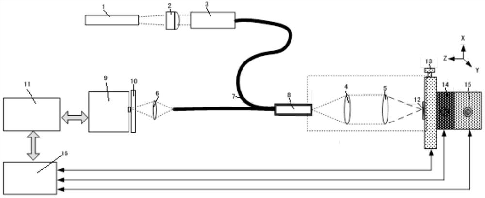
[0035] A workpiece surface microtopography measuring device coated with cutting fluid, such as figure 1 As shown, it consists of laser 1, collimating lens 2, laser coupler 3, lens I4, lens II5, lens III6, Y-shaped fiber 7, fiber coupler 8, spectrometer 9, long-pass filter 10, computer 11, and X-axis The motion table 13, the Y-axis motion table 14, the Z-axis motion table 15, and the motion controller 16 are composed. The laser 1 is collimated by the collimator lens 2, coupled into the Y-shaped optical fiber 7 by the laser coupler 3, outputs the laser light through the fiber coupler 8, and then focuses on the workpiece sample through the optical fiber confocal optical path composed of lens 4 and lens 5 Surface; the cutting fluid on the surface of the sample is excited by the laser to generate fluorescence, and the scattered fluorescence returns to the Y-shaped optical fiber 7 through the confocal optical path of the optical fiber, and is focused by the lens 6. After the laser w...


PUM


Abstract

A workpiece surface microtopography measurement device and measurement method covered with cutting fluid, belonging to the technical field of mechanical automation, including lasers, collimating lenses, laser couplers, lens I, lens II, lens III, Y-shaped optical fibers, and optical fiber couplers , spectrometer, long-pass filter, computer, X-axis motion table, Y-axis motion table, Z-axis motion table and motion controller, use laser to excite the cutting fluid on the surface of the workpiece to generate fluorescence, collect spectral signals through the computer, perform peak analysis, and obtain The thickness at the sampling point of the cutting fluid film is scanned through the interaction between the computer and the motion controller to scan the entire surface of the workpiece to complete the measurement of the microscopic topography of the entire workpiece surface covered with cutting fluid. In the state where the surface of the workpiece sample is covered with cutting fluid, the invention does not need to remove the workpiece for cleaning, and measures the shape of the workpiece surface on-site, avoiding the secondary clamping error caused by traditional off-line measurement, and covering the surface of the workpiece with cutting fluid for wet cutting Shape measurement provides new technical means.

Description

technical field [0001] The invention belongs to the technical field of mechanical automation, and in particular relates to a measuring device and a measuring method for the surface micro-topography of a workpiece coated with cutting fluid. Background technique [0002] In the process of high-speed micro-milling, the online in-situ measurement of workpiece surface topography directly affects the control of workpiece processing parameters and the final workpiece surface processing quality. Since the current processing method is mainly wet cutting, cutting fluid is required to participate in tool lubrication and cooling during workpiece processing, and the cutting fluid film will remain on the surface of the workpiece after processing, resulting in the in-situ on-line detection of the microscopic morphology of the workpiece surface. difficulty. Existing methods for removing the cutting fluid film include air blowing, alcohol scrubbing, ultrasonic cleaning, etc. The air blowing...

Claims


Application Information

Patent Timeline
Patent Type & Authority Patents(China)
IPC IPC(8): G01B11/24
Inventor 于占江于化东许金凯冯磊李金哲张向辉江海宇
Owner CHANGCHUN UNIV OF SCI & TECH
Learn More