Laser range finder
A laser rangefinder and laser receiving technology, which is applied in the field of laser rangefinders, can solve the problems of reduced distance accuracy and achieve the effect of improving distance measurement accuracy
- Summary
- Abstract
- Description
- Claims
- Application Information
AI Technical Summary
Problems solved by technology
Method used
Image
Examples
no. 1 example
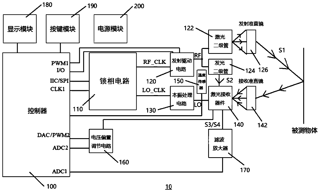
[0042] figure 1 A schematic diagram of the overall structure of the first laser range finder 10 provided in the embodiment of the present application is shown. refer to figure 1 , the laser range finder 10 includes a controller 100, a phase-locked circuit 110, an emission drive circuit 120, a laser diode 122 (i.e. the first emission tube), a light emitting diode 124 (i.e. the second emission tube), a local oscillator processing circuit 130 and a laser receiving device 140 .
[0043] The controller 100 is a unit with computing and processing capabilities. The controller 100 has multiple functional pins externally, which can be connected to other components for signal transmission and to realize corresponding functions. The controller 100 may be implemented by, but not limited to, a single-chip microcomputer (Micro Controller Unit, MCU), such as an STM32 series single-chip microcomputer. It can be understood that during specific implementation, the controller 100 used should ...
no. 2 example
[0071] Figure 5 A schematic diagram of the overall structure of the second laser rangefinder 20 provided in the embodiment of the present application is shown. refer to Figure 5 , the laser rangefinder 20 includes a controller 100, a phase-locked circuit 110, an emission drive circuit 120, a first light-emitting diode 123 (i.e. the first emission tube), a second light-emitting diode 125 (i.e. the second emission tube), a local oscillator processing The circuit 130 and the laser receiving device 140.
[0072] The phase-locking circuit 110 is respectively connected to the clock pin of the controller 100, the emission driving circuit 120 and the local oscillator processing circuit 130, for outputting the synchronous clock signal to the controller 100, and outputting the driving clock signal to the emission driving circuit 120 , and output the local oscillator clock signal to the local oscillator processing circuit 130;
[0073] The emission driving circuit 120 is also connec...
PUM
 Abstract
Description
Claims
Application Information
 - R&D
- Intellectual Property
- Life Sciences
- Materials
- Tech Scout
- Unparalleled Data Quality
- Higher Quality Content
- 60% Fewer Hallucinations
Browse by: Latest US Patents, China's latest patents, Technical Efficacy Thesaurus, Application Domain, Technology Topic, Popular Technical Reports.
© 2025 PatSnap. All rights reserved.Legal|Privacy policy|Modern Slavery Act Transparency Statement|Sitemap|About US| Contact US: help@patsnap.com


