Load terminal for high voltage direct current relay
A load terminal, high-voltage DC technology, applied in relays, electromagnetic relays, electromagnetic relay details, etc., can solve the problems of load terminal slippage, brazing failure, and easy aging of glue, so as to reduce the possibility of failure and improve welding. The effect of firmness and improved reliability of use
- Summary
- Abstract
- Description
- Claims
- Application Information
AI Technical Summary
Problems solved by technology
Method used
Image
Examples
Embodiment 1
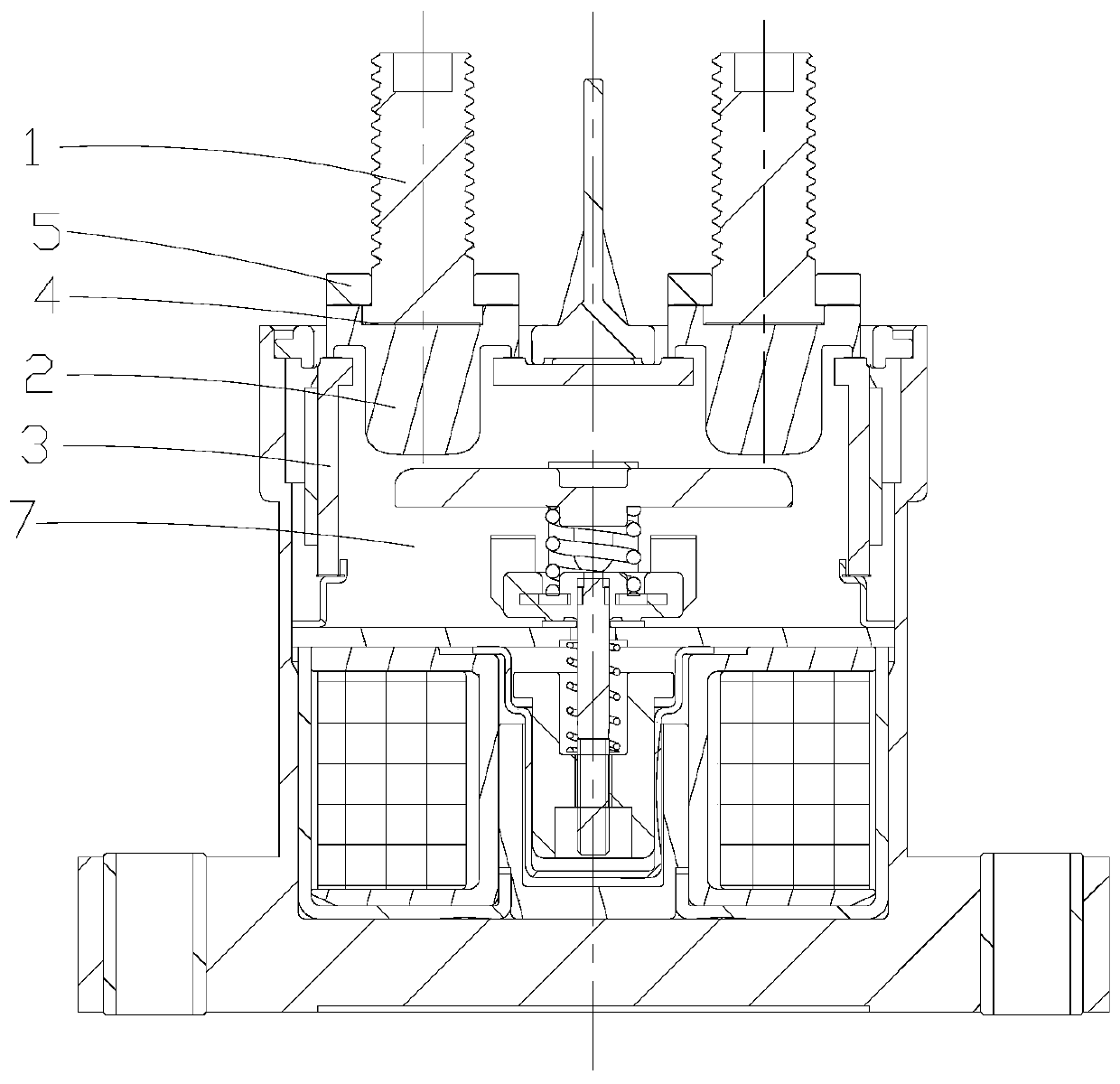
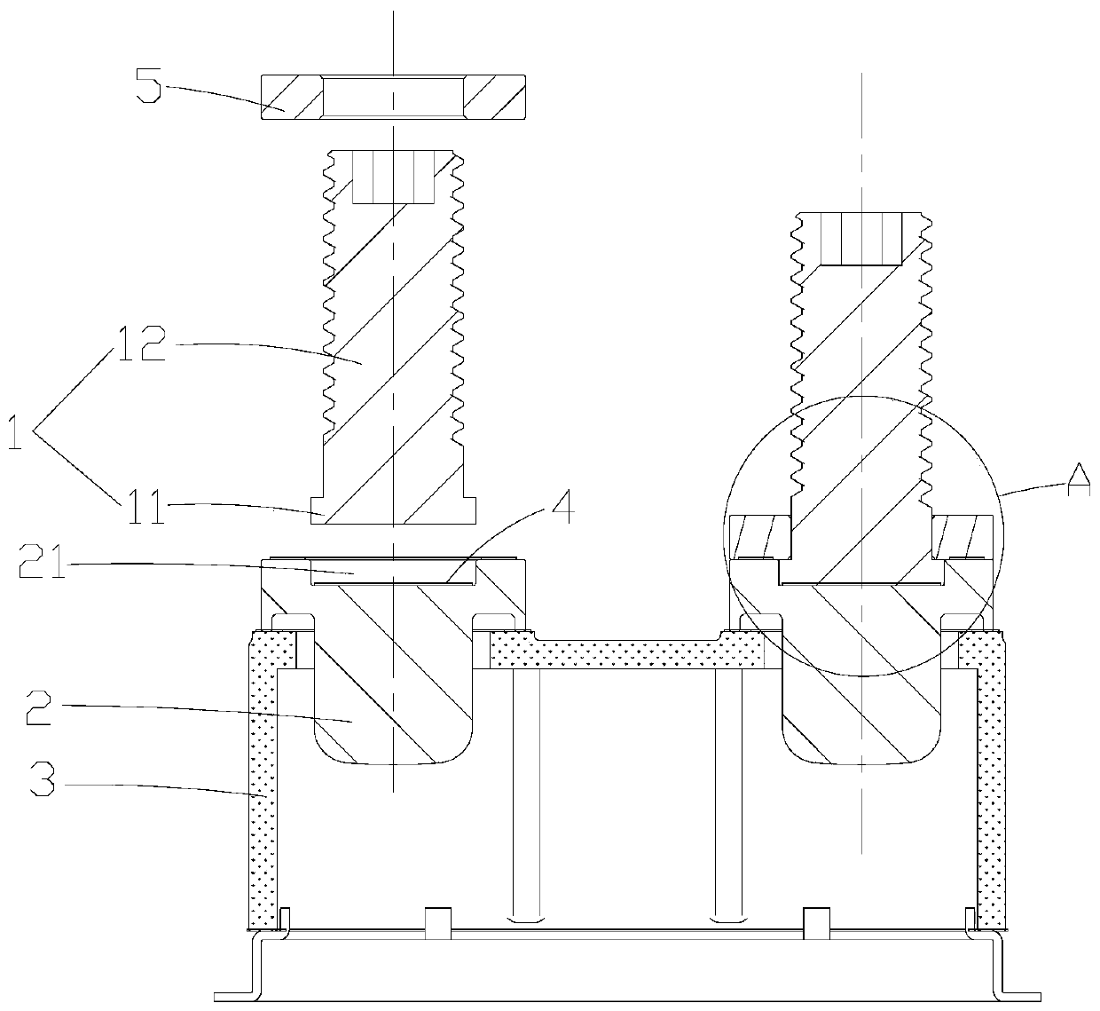
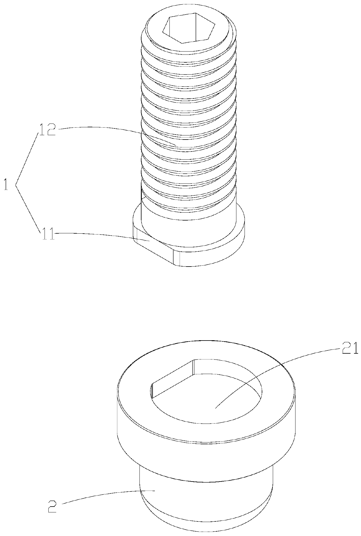
[0048] Please refer to the attached figure 1 Attached Figure 8 In this embodiment, a load terminal of a high-voltage DC relay includes a connecting end 1 and a leading end 2 arranged on the relay ceramic cover 3 of the relay 7. The leading end 2 is provided with a containing slot 21 on the head, and the connecting end The lower part of 1 forms a flange portion 11 and can be fitted into the accommodating groove 21, the flange portion 11 and the bottom surface of the accommodating groove 21 are connected by brazing layer 4, the hole of the accommodating groove 21 The mouth is provided with a pressure block 5 that can be matched with the flange portion 11. The pressure block 5 is fixedly connected to the head of the lead-out end 2, and the flange portion 11 can be pressed in the housing through the cooperation of the pressure block 5 and the flange portion 11 In the groove 21 to prevent the connecting end 1 from falling off. In this embodiment, preferably, the lead-out end 2 is f...
Embodiment 2
[0055] Please refer to the attached Picture 10 The difference between this embodiment and the first embodiment is that in this embodiment, an annular concave portion 6 is formed on the bottom surface of the flange portion 11 to form an annular boss structure on the outer peripheral edge of the bottom surface, and A circular boss structure is formed at the center of the bottom surface. During welding, the circular boss structure and the annular boss structure can cooperate with the bottom surface of the accommodating groove 21 to form a circular welding surface and a ring shape. The welding surface can be reduced by the recess 6 to reduce welding stress during welding and ensure the welding quality, and the solder of the brazing layer 4 can accumulate on the inner wall of the recess 6 during welding to improve the welding firmness.
Embodiment 3
[0057] Please refer to the attached Picture 11 The difference between this embodiment and the first embodiment is that, in this embodiment, two coaxially arranged annular recesses 6 are formed on the bottom surface of the flange portion 11 so that two annular bosses are formed on the bottom surface. Structure, and a circular boss structure is formed at the center of the bottom surface. During welding, the circular boss structure and the two annular boss structures can respectively cooperate with the bottom surface of the accommodating groove 21 to form a circular The welding surface and the two annular welding surfaces can be reduced by the recess 6 to reduce the welding stress during welding and ensure the welding quality, and the solder of the brazing layer 4 can accumulate on the inner wall of the recess 6 during welding to improve welding Firmness.
PUM
 Abstract
Description
Claims
Application Information
 - R&D
- Intellectual Property
- Life Sciences
- Materials
- Tech Scout
- Unparalleled Data Quality
- Higher Quality Content
- 60% Fewer Hallucinations
Browse by: Latest US Patents, China's latest patents, Technical Efficacy Thesaurus, Application Domain, Technology Topic, Popular Technical Reports.
© 2025 PatSnap. All rights reserved.Legal|Privacy policy|Modern Slavery Act Transparency Statement|Sitemap|About US| Contact US: help@patsnap.com


