
Automatic feeding device for sheep breeding

An automatic and feed technology, applied in animal feeding devices, applications, animal husbandry, etc., can solve the problems of low feed utilization rate, increase, and decrease of mutton output rate.

Pending Publication Date: 2019-06-25
HENAN UNIV OF SCI & TECH
View PDF0 Cites 9 Cited by
  • Summary
  • Abstract
  • Description
  • Claims
  • Application Information

AI Technical Summary

Problems solved by technology

However, under the premise that the house-feeding breeding mode brings many conveniences, since the house-feeding breeding mode is still in the promotion stage, there are problems such as breeding management, technology and other immature applications, which will not only bring changes to farmers, but also Causes a decrease in the slaughter rate of sheep, which leads to a decrease in the output rate of mutton
The construction of the traditional sheep shed area is random, the feeding method is extensive, and the utilization rate of the feed is relatively low, which will cause waste of feed, and the environmental pollution caused by the waste of feed will make the breeding environment condition worse and cause the sheep to get sick. The increase in probability is not conducive to increasing the output rate of mutton. In contrast, the construction of large-scale farm facilities requires a large amount of capital investment, and the cost is too high, beyond the economic tolerance of most farmers and herdsmen

Method used


Image

  • Automatic feeding device for sheep breeding
  • Automatic feeding device for sheep breeding
  • Automatic feeding device for sheep breeding

Examples


specific Embodiment approach

[0031] Referring to the accompanying drawings, the specific implementation is as follows:

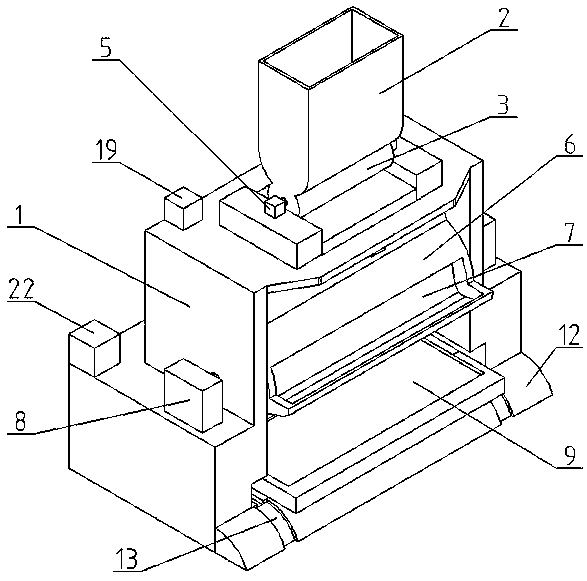
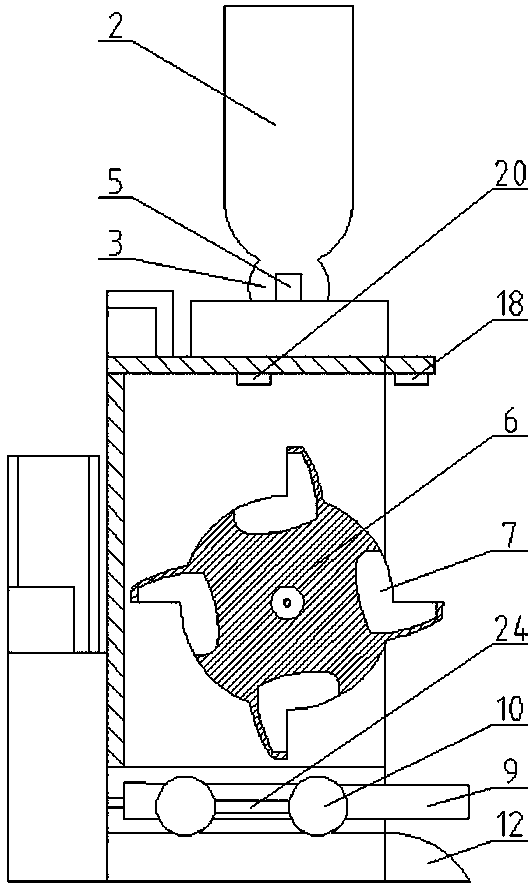
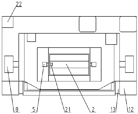
[0032]An automatic feeding device for sheep breeding, comprising a housing 1, a feed box 2 is provided on the top of the housing 1, a discharge cavity 3 is provided at the bottom of the feed tank 2, and a feed box capable of sealing the feed box is provided in the discharge cavity 3 2 The fan-shaped body rotating shaft 4 of the bottom discharge port, the top of the housing 1 is also provided with a first motor 5 that can drive the fan-shaped body rotating shaft 4 to rotate; the fan-shaped body rotating shaft 4 is horizontally arranged, and the discharge port at the bottom of the feed box 2 is a A rectangular mouth arranged axially along the fan shaft 4; the sector angle of the fan shaft 4 is 90°, the discharge chamber 3 is a cylindrical structure, and the inner diameter of the discharge chamber 3 is the same as that of the fan shaft 4 The outer wall matches.

[0033] A feeding wheel 6 ...


PUM


Abstract

Provided is an automatic feeding device for sheep breeding. A feed box is arranged at the top of a shell, a discharging cavity is formed in the bottom of the feed box, a sector rotary shaft capable ofsealing a discharging opening in the bottom of the feed box is arranged in the discharging cavity, and a feeding wheel is arranged in the shell. Four bosses are arranged on the feeding wheel in the circumferential direction at equal intervals, and a feed groove is formed. A feed collecting trolley for bearing feed flowing out of the feed groove is arranged at the bottom of the shell, a sector step is arranged on one side of the bottom of the shell, and therefore the feed collecting trolley can move obliquely downwards after moving to the sector step; an airbag for pushing the feed collectingtrolley to move towards the sector step is arranged at the bottom of the shell, and a gas compressing device for inflating the airbag and a gas collecting chamber for collecting gas exhausted by the airbag are arranged on the shell. A spring is connected between the side wall, towards the airbag, of the feed collecting trolley and the inner wall of the shell, and used for pulling the feed collecting trolley to the original position through the elastic acting force when the feed on the feed collecting trolley moving to the sector step is eaten by sheep to cause weight reduction of the feed collecting trolley.

Description

technical field [0001] The invention relates to the field of feeding devices, in particular to an automatic feeding device for sheep breeding. Background technique [0002] Animal husbandry is an important part of my country's agriculture. my country's animal husbandry accounts for more than 30% of the total agricultural output value. The vigorous development of animal husbandry will increase farmers' income, develop rural economy, meet meat demand and improve people's quality of life, etc. There is a great impetus. my country is a big sheep raising country with a long history of raising sheep. Because of the different geographical conditions and climate environments in different regions, the raising patterns of sheep are also different. There are three main feeding modes of sheep: house feeding, grazing and semi-grazing and half house feeding. The rapid development of the sheep raising industry is inseparable from the feeding mode. House feeding is a large-scale, intensive...

Claims


Application Information

Patent Timeline
IPC IPC(8): A01K5/02
CPCY02P60/87
Inventor 周罕觅王升升姚昊明解晓琳燕辉赵龙张洋
Owner HENAN UNIV OF SCI & TECH
Learn More