
A longitudinal bar feeding device for steel cage welding

A technology of feeding device and steel cage, applied in welding equipment, auxiliary device, auxiliary welding equipment, etc., can solve the problems of low production efficiency, high labor cost, poor precision control, etc., to improve production efficiency, high degree of automation, guarantee The effect of precision

Active Publication Date: 2021-04-13
CHINA MINSHENG ZHUYOU
View PDF7 Cites 0 Cited by
  • Summary
  • Abstract
  • Description
  • Claims
  • Application Information

AI Technical Summary

Problems solved by technology

This operation method of longitudinal bar transfer and feeding requires manual participation, and the spacing between longitudinal bars needs to be placed and controlled manually. The precision control is poor, time-consuming and laborious, the production efficiency is relatively low, and the labor cost is high.

Method used


Image

  • A longitudinal bar feeding device for steel cage welding
  • A longitudinal bar feeding device for steel cage welding
  • A longitudinal bar feeding device for steel cage welding

Examples


Embodiment 1

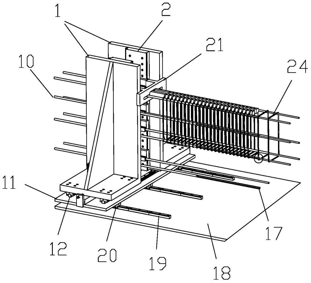
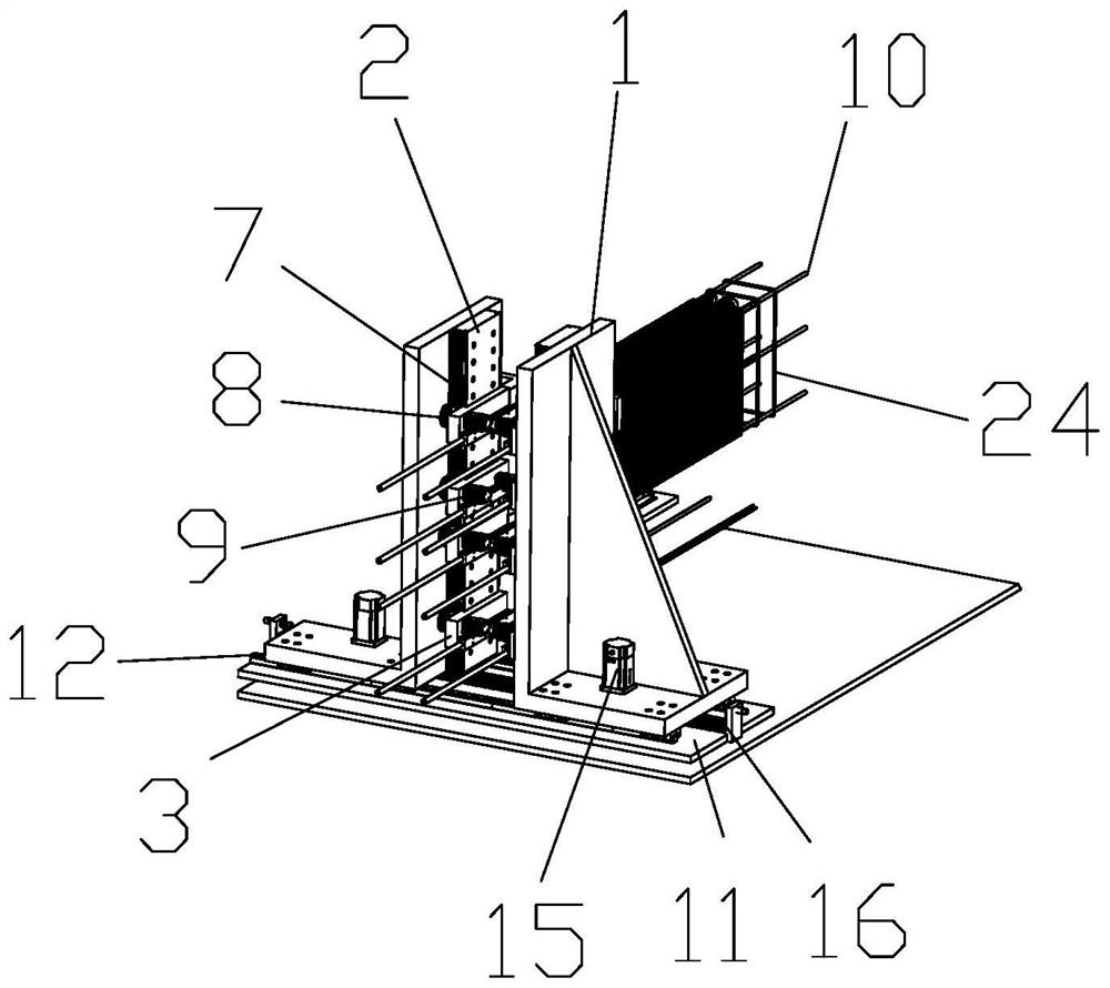
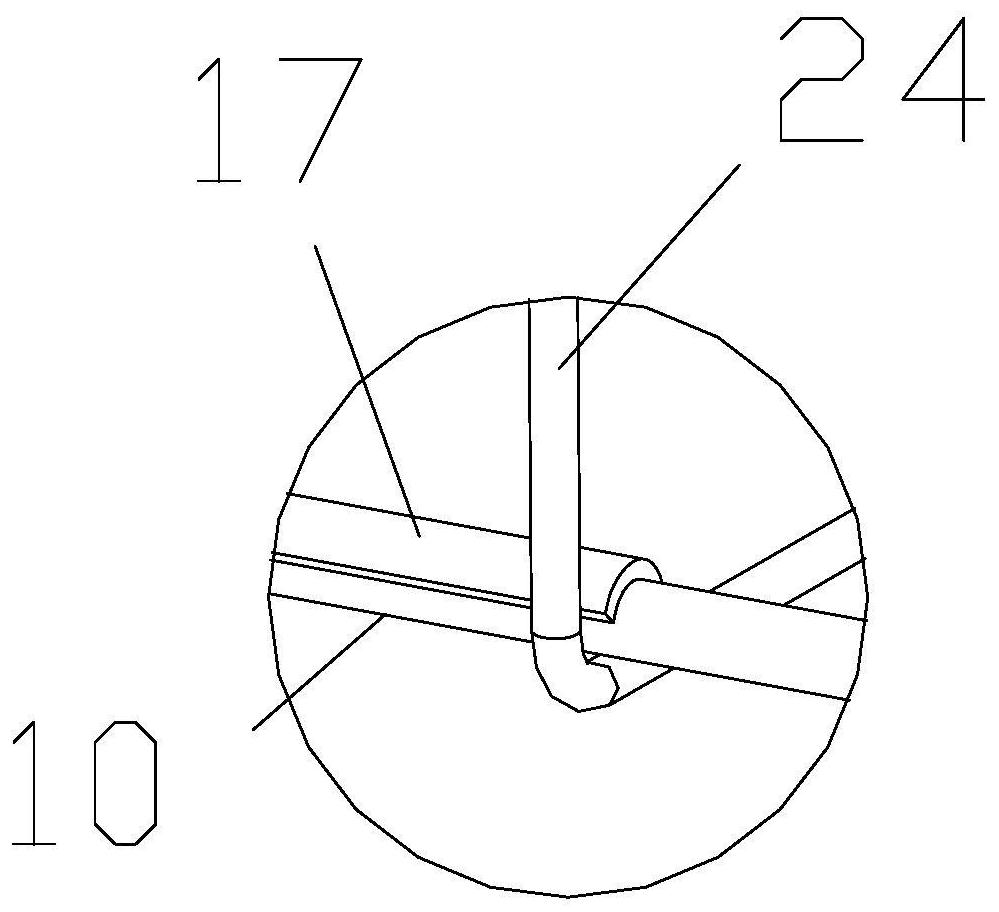
[0034] Reference figure 1 and figure 2 , the longitudinal bar feeding device for steel cage welding in this embodiment includes a bracket, a Y-axis guide rail 2 fixed on the bracket, a plurality of sliders 3 arranged on the Y-axis guide rail 2, a driving motor 4 and a friction wheel set 5. The bracket includes two opposite fixed plates 1, and the opposite inner surfaces of the two fixed plates 1 are respectively provided with Y-axis guide rails 2 and sliders 3, and the sliders 3 are provided with horizontal slots 6 for fixing longitudinal ribs 10, Y-axis guide rails 2. A vertical rack 7 is arranged on one side, and a Y-axis motor 9 and a vertical gear 8 cooperating with the vertical rack 7 are fixed on the slider 3. The Y-axis motor 9 and the vertical gear 8 are connected through a horizontal axis. The shaft motor 9 drives the vertical gear 8 to move on the vertical rack 7 . In this way, by arranging the Y-axis motor 9 and the rack and pinion group, a plurality of sliders ...


PUM


Abstract

The invention discloses a longitudinal reinforcement feeding device for steel cage welding, which is used for conveying longitudinal reinforcement in the horizontal direction, comprising a bracket, a Y-axis guide rail fixed on the bracket, a plurality of sliders arranged on the Y-axis guide rail, a driving The motor and the friction wheel set; the bracket includes two opposite fixed plates, and the opposite inner surfaces of the two fixed plates are respectively provided with Y-axis guide rails and sliders, and the sliders are provided with horizontal slots for fixing longitudinal ribs, and the drive motor drives the friction The wheel set rotates; a vertical rack is installed on one side of the Y-axis guide rail, and a Y-axis motor and a vertical gear that cooperates with the vertical rack are fixed on the slider. The Y-axis motor drives the vertical gear to move on the vertical rack . In this device, the friction wheel group presses the longitudinal ribs, and the motor drives the friction wheel group to rotate, and the transmission of the longitudinal ribs in the horizontal direction is realized through the friction force; the longitudinal ribs can be transported to the steel cage welding equipment according to the production cycle, and the production efficiency is improved. .

Description

technical field [0001] The invention belongs to the technical field of reinforcement cage processing machinery in construction, in particular, the invention relates to a longitudinal reinforcement feeding device for welding reinforcement cages. Background technique [0002] In the prior art, steel cages are mostly completed by machine welding in factories. After the raw materials of stirrups and longitudinal bars are processed separately, they are transported to the welding equipment to weld the stirrups to the longitudinal bars to form a stirrup cage. In the processing and transportation of longitudinal bars, the disc-shaped steel bars are straightened and then cut to a specific length, and then sent to the longitudinal bar support rack of the welding equipment, and then the single longitudinal bar is manually placed in the steel cage The specified spacing is placed under the wire grabbing mechanism, and the multiple grabbing clamps of the wire grabbing mechanism move down...

Claims


Application Information

Patent Timeline
Patent Type & Authority Patents(China)
IPC IPC(8): B23K37/00
Inventor 黄岸薛英杰
Owner CHINA MINSHENG ZHUYOU
Learn More