Machining method of hollow plunger

A processing method and plunger technology, which is applied in the field of hollow plunger processing, can solve the problems of poor stability of plunger pumps and large plunger body mass, and achieve the effects of improved efficiency, high degree of automation, and light weight

Pending Publication Date: 2019-06-25
四川坤成润科技有限公司
View PDF0 Cites 4 Cited by
  • Summary
  • Abstract
  • Description
  • Claims
  • Application Information

AI Technical Summary

Problems solved by technology

[0004] The object of the present invention is to provide a processing method for a hollow plunger, which solves the

Method used


Image

  • Machining method of hollow plunger
  • Machining method of hollow plunger
  • Machining method of hollow plunger

Examples


Embodiment 1

[0048] A method for processing a hollow plunger provided by a preferred embodiment of the present invention includes the following steps in sequence:

[0049] S1: if figure 1 As shown, select the bar material according to the size of the plunger body;

[0050] S2: performing softening treatment after blanking the bar in step S1;

[0051] S3: performing surface treatment on the softened bar in step S2;

[0052] S4: lubricate the bar after surface treatment in step S3;

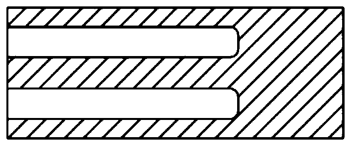
[0053] S5: if figure 2 , image 3 As shown, the lubricated bar in step S4 is cold extruded to form the upper part of the plunger body and the lower part of the plunger body;

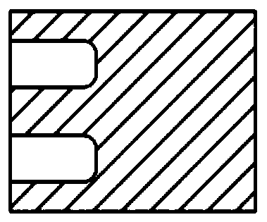
[0054] S6: if Figure 4 As shown, process the ball head and lubricating hole on the upper part of the plunger body, process the lower part of the plunger body and the middle lubricating hole;

[0055] S7: if Figure 6 As shown, the upper part of the plunger body and the lower part of the plunger body are friction welded;

[0056]...

Embodiment 2

[0064] In this embodiment, on the basis of Embodiment 1, the phosphating treatment device includes a phosphating treatment unit and a pushing mechanism. A processing pool is arranged between them, and the processing pool includes a first processing pool 2 and a second processing pool 3, and the first processing pool 2 is located above the second processing pool 3; the side plate 1 is provided with a rail groove, and the The guide rail groove is arranged along the horizontal direction, and the guide rail groove includes a first guide rail groove 101 and a second guide rail groove 102, and the first guide rail groove 101 and the second guide rail groove 102 are symmetrical about the horizontal central axis of the side plate 1, and the first processing The two ends of pool 2 are provided with the first slide block 201 that matches with the first rail groove 101, and described first slide block 201 is provided with first projection 202; The two ends of described second treatment po...


PUM

PropertyMeasurementUnit
Surface hardnessaaaaaaaaaa

Abstract

The invention discloses a machining method of a hollow plunger, and belongs to the technical field of hollow plunger machining. The machining method includes the sequentially-conducted steps that a bar material is selected; the bar material is subjected to softening processing after being subjected to blanking; surface processing is conducted on the bar material subjected to softening processing;lubricating processing is conducted on the bar material subjected to surface processing; cold extruding is conducted on the bar material subjected to lubricating processing to form a plunger body upper portion and a plunger body lower portion; a ball head and a lubrication hole of the plunger body upper portion are machined, and the plunger body lower portion and a middle lubrication hole are machined; the plunger body upper portion and the plunger body lower portion are welded in a friction welding manner; friction welding flashes are subjected to rough turning; hardening and tempering processing and nitriding processing are conducted on a plunger body obtained after welding is completed; and outer circles of the ball head and the plunger body are ground, and machining of the hollow plunger is completed. The plunger body machined and formed through the machining method is small in thermal expansion amount, the influence of temperature on changes of the fit clearance of the plunger outer diameter and a cylinder body is small, and therefore stability of a plunger pump is improved.

Description

technical field [0001] The invention belongs to the field of hollow plunger processing, and relates to a processing method of a hollow plunger. Background technique [0002] The plunger pump is an important device in the hydraulic system. It relies on the reciprocating movement of the plunger in the cylinder to change the volume of the sealed working chamber to realize oil absorption and oil pressure. The plunger pump has the advantages of high rated pressure, compact structure, high efficiency and convenient flow adjustment. Piston pumps are widely used in high pressure, large flow and occasions where the flow needs to be adjusted, such as hydraulic presses, engineering machinery and ships. [0003] According to the different plunger body, the plunger pump is generally divided into single plunger pump, horizontal plunger pump, axial plunger pump and radial plunger pump. The plunger body of the existing plunger pump is mostly a solid structure, the weight is relatively la...

Claims


Application Information

Patent Timeline
IPC IPC(8): B23P15/00
Inventor 任荣智李志刚何小平
Owner 四川坤成润科技有限公司
Why Eureka
Try Eureka