Laser quenching machine for gear

A laser quenching and gear technology, applied in quenching devices, heat treatment equipment, furnaces, etc., can solve the problems of affecting quenching efficiency, affecting the quality of gears, and troublesome quenching operations, so as to ensure work efficiency, uniform and reliable cooling, and firm and reliable installation. Effect

Pending Publication Date: 2019-06-25
杭州智钒激光科技有限公司
View PDF0 Cites 11 Cited by
  • Summary
  • Abstract
  • Description
  • Claims
  • Application Information

AI Technical Summary

Problems solved by technology

[0002] In the process of gear processing, there is a quenching process, which requires special quenching equipment to quench the gears. The existing quenching equipment is usually that the gears are directly fixed on the gear mounting table, and the fixed gear is translated and rotated by the mobile quenching tool. The gear is quenched, which is troublesome, which affects the quenching efficiency, and the uniformity and reliability of the tooth surface quenching cannot be guaranteed;
[0003] The general gears of the existing quenching equipment are installed on the gear installation turntable of the quenching equipment. The gear installation turntable drives the gear to rotate to the designated position and then performs quenching operation. Since the gear installation turntable can rotate freely, it is easy to cause the gear position during the quenching operation. Deviation not only affects the quenching efficiency, but also affects the quenching effect and product quality;
[0004] Conventional gears are directly installed on the gear installation turntable of the quenching equipment for quenching operation. However, since the shaft teeth have gear shafts on both sides of the gear, during the rotation process, the gear shaft will generate outward centrifugal force. The gear mounting plate fixes the gears, and the installation stability of the gears cannot be guaranteed. During the quenching operation, it is easy to cause the position of the gears to deviate, which not only affects the quenching efficiency, but also affects the quenching effect and product quality;
[0005] Conventional quenching equipment, because the gear only rotates during the quenching process, it cannot be moved. In order to ensure that the gear installation station is spacious and convenient for gear disassembly,

Method used


Image

  • Laser quenching machine for gear
  • Laser quenching machine for gear
  • Laser quenching machine for gear

Examples


Embodiment Construction

[0055] The present invention will be described in further detail below in conjunction with the accompanying drawings, but it is not intended to limit the protection scope of the present invention.

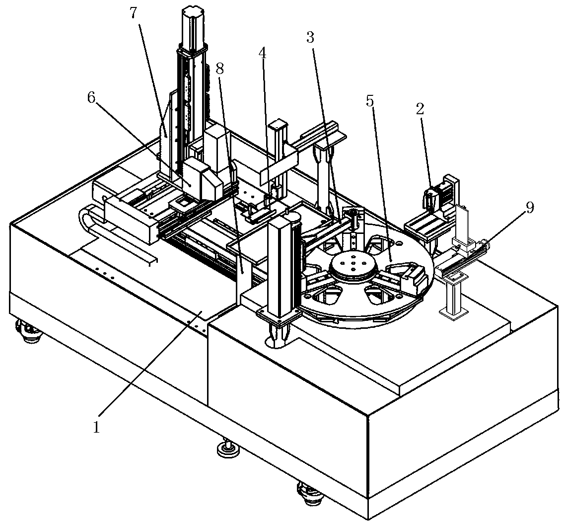
[0056] Such as figure 1 As shown, a gear laser quenching machine includes a quenching platform 1, a gear installation turntable 5 installed on the quenching platform 1, a laser head 6, a gear positioning mechanism 2, a top mechanism 3, a laser head moving device 7, a cooling mechanism 4, Coolant recovery mechanism 8 and cleaning mechanism 9;

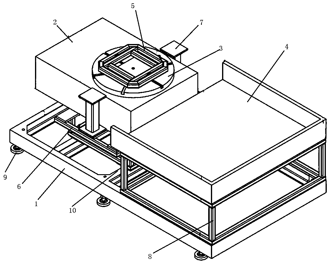
[0057] Such as figure 2 As shown, the quenching platform includes a base 1, a four-axis rotary table 2 installed on the base for installing a gear installation turntable, and a laser head installation table 4 for installing a laser head. The height of the laser head installation table 4 is the same as that of the four-axis rotation The height of table 2 is matched, and the four-axis rotary table 2 is provided with a turntable mounting fram...


PUM


Abstract

The invention discloses a laser quenching machine for a gear. The machine comprises a quenching platform, a gear mounting turntable, a laser head, a gear positioning mechanism, a centre mechanism, a laser head moving device, a cooling mechanism, a cooling liquid recovering mechanism and a sweeping mechanism, wherein the quenching platform comprises a base, a four-axis rotating platform and a laserhead mounting platform; the gear positioning mechanism is used in match with the gear mounting turntable and comprises a positioning head, a positioning cylinder and a positioning frame; the centre mechanism is used in match with the gear mounting turntable and comprises a vertical supporting column and a centre lead screw transmission mechanism; the laser head moving device comprises an up-downmoving mechanism, a forward-backward moving mechanism and a leftward-rightward moving mechanism; the cooling mechanism comprises a cooling liquid spray head, a solenoid valve, a spraying head liftingstructure and a water baffle; the cooling liquid recovering mechanism comprises a cooling liquid recovering groove; and the sweeping mechanism comprises an air port, an up-down moving mechanism and aforward-backward moving mechanism. The machine is capable of sweeping gear teeth with different diameter and thickness, so that the quenching efficiency, the quenching effect and the product quality are ensured; and the applicable scope is wide.

Description

technical field [0001] The invention relates to parts of gear processing equipment, in particular to a gear laser quenching machine. Background technique [0002] In the process of gear processing, there is a quenching process, which requires special quenching equipment to quench the gears. The existing quenching equipment is usually that the gears are directly fixed on the gear mounting table, and the fixed gear is translated and rotated by the mobile quenching tool. The gear is quenched, which is troublesome, which affects the quenching efficiency, and the uniformity and reliability of the tooth surface quenching cannot be guaranteed; [0003] The general gears of the existing quenching equipment are installed on the gear installation turntable of the quenching equipment. The gear installation turntable drives the gear to rotate to the designated position and then performs quenching operation. Since the gear installation turntable can rotate freely, it is easy to cause the...

Claims


Application Information

Patent Timeline
IPC IPC(8): C21D1/667C21D9/32
Inventor 黄世凡蒋明明
Owner 杭州智钒激光科技有限公司
Why Eureka
Try Eureka