Gas burner for conversion furnace

A gas burner and reformer technology, applied in the direction of gas fuel burners, burners, combustion methods, etc., can solve the problems of reducing the flame peak temperature, failing to meet emission standards, and effectively reducing NOx emissions, etc., to achieve uniform flow, The effect of reducing the peak flame temperature

Inactive Publication Date: 2019-06-25
陕西宏远流体控制设备有限公司
View PDF0 Cites 0 Cited by
  • Summary
  • Abstract
  • Description
  • Claims
  • Application Information

AI Technical Summary

Problems solved by technology

[0003] The combustion-supporting air temperature of the top-burning furnace can generally reach 450°C, and the highest can reach 600°C. At high temperatures, the N in the air 2 It will be oxidized into NOx. The current fuel for top-burning furnaces generally uses low-pressure fuel gas produced by the device, and the part with insufficient heat is supplemented with high-pressure fuel gas. Among them, low-pressure fuel gas accounts for about 90% of the total heat release, and high-pressure fuel gas accounts for 90% of the total heat release. About 10%, the current top-burning furnace burner sets the high-pressure fuel air gun and the low-pressure fuel air gun into a coaxial structure, arranged on the axis of the fire channel, adopts a single injection of fuel, and cooperates with air classification technology, and only relies on air The staging technology cannot significantly reduce the flame peak temperature, so this type of burner cannot effectively reduce NOx emissions and cannot meet the increasingly higher emission standards
[0004] NOx emission data is an important parameter to characterize the performance of the burner. The upcoming "Comprehensive Emission Standard of Air Pollutants" will limit the NOx emission of petrochemical tubular heating furnaces to less than 100mg / m 3 (48.8PPm), currently most burners will not be able to meet this requirement

Method used


Image

  • Gas burner for conversion furnace
  • Gas burner for conversion furnace

Examples


Embodiment Construction

[0017] The present invention will be described in detail below in conjunction with the accompanying drawings.

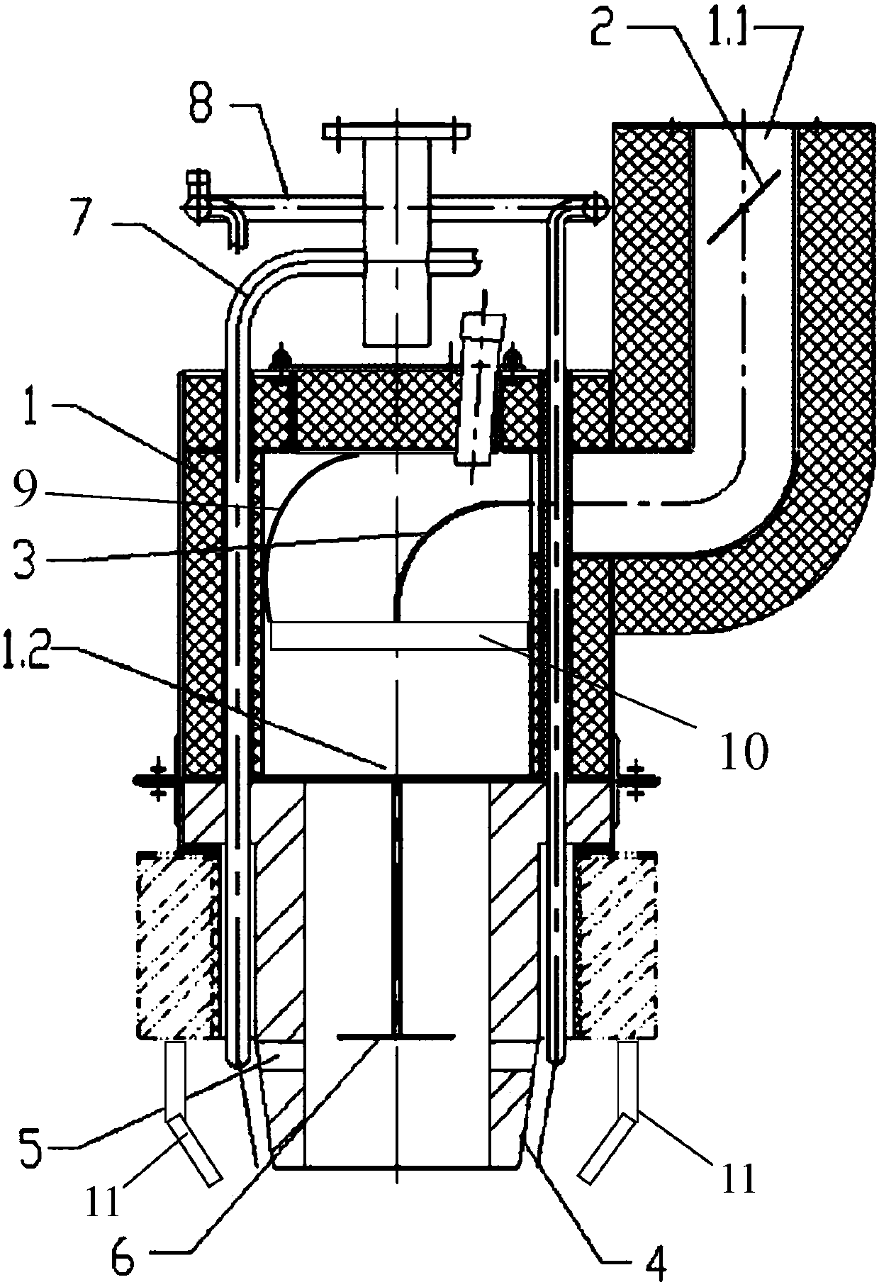
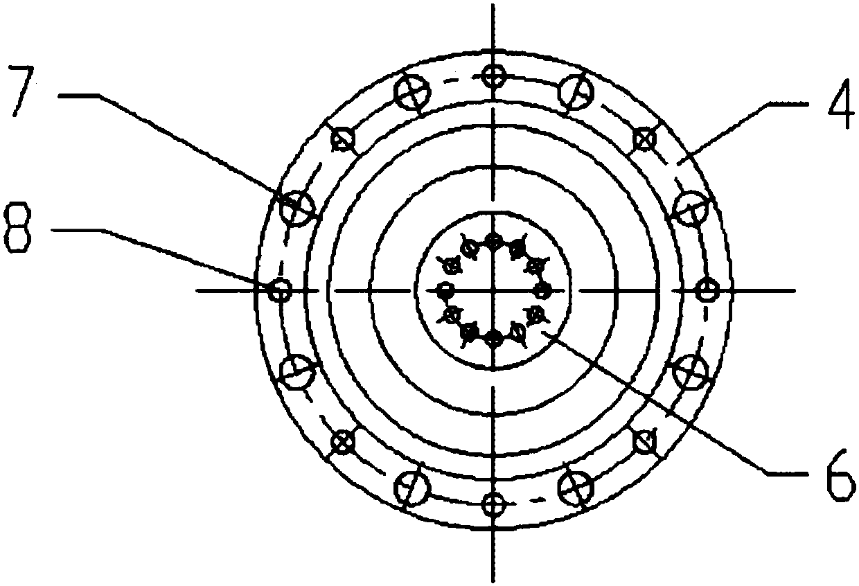
[0018] see Figure 1-2 , a gas burner for a reformer, including a housing 1, the upper part of the housing 1 is provided with an air inlet 1.1, the burner also includes a low-pressure fuel air gun 7 and a high-pressure fuel air gun 8, a low-pressure fuel air gun 7 and a high-pressure fuel air gun 8 passes through the shell 1 and is evenly distributed on the outside of the refractory brick 4 in a staggered manner; it is characterized in that: the first air deflector 3 and the second air deflector 9 with an arcuate surface are arranged in the shell 1, so The first air deflector 3 is arranged at the air inlet of the casing 1, and the second air deflector 9 is arranged on the inner wall opposite to the air inlet of the casing 1; the first air deflector 3 and The second air deflector 9 is used to guide the wind entering the air inlet downward; a number of splitter vanes ...


PUM


Abstract

The invention relates to a gas burner for a conversion furnace. The gas burner comprises an air outlet system and a filtering system. The air outlet system comprises an annular cylinder, two air outlet pipes communicate with the outer side of the annular cylinder, and a bolt and an adjusting nut for adjusting the height are arranged below the air outlet pipes. The annular cylinder is fixed on a shell of the filtering system through a sealing gasket and an upper flange, the filtering system is arranged below the annular cylinder, a pull rod is arranged at the center of a filter element, the pull rod is formed by connecting an upper pull rod and a lower pull rod, and a tension sensor is arranged between the upper pull rod and the lower pull rod. The gas burner is simple in structure, low incost and good in filtering effect. The technological requirements of a dry method converter in the nuclear energy industry can be completely met, and a pressure sensor is arranged on the pull rod, thepull force of the pull rod can be accurately detected, and the control over the filtering system is accurately ensured.

Description

technical field [0001] The invention relates to a burner of a reforming furnace, in particular to a burner of a top-burning furnace. It belongs to the technical field of combustion equipment. Background technique [0002] In recent years, a large number of large-scale reformers have been put into production in my country. The reformers are classified according to the heating mode of the radiation chamber, which can be divided into the following four ways: 1. Top-fired furnace; 2. Side-fired furnace; 3. Ladder furnace; 4. Bottom-fired furnace stove. Among them, the top-fired furnace is the most widely used type of furnace. The burners of this type of furnace are arranged on the top of the radiation chamber. The heating form of the conversion tube is a single row of tubes receiving double-sided radiation. The flame is parallel to the furnace tube and burns vertically downward. , the flue gas descends and leaves the radiation chamber from the flue at the bottom of the furnace,...

Claims


Application Information

Patent Timeline
Patent Type & Authority Applications(China)
IPC IPC(8): F23D14/26F23D14/70
Inventor 韩晋平刘保荣廖红春
Owner 陕西宏远流体控制设备有限公司
Why Eureka
Try Eureka