Vehicle motor with charging control function

A charging control and function technology, applied in the field of vehicle motors with built-in charging control function, can solve the problems of low transmission efficiency, increased power transmission loss, and increased circuit configuration complexity.

Inactive Publication Date: 2019-06-25
CHINA MOTOR CORPORATION +1
View PDF8 Cites 0 Cited by
  • Summary
  • Abstract
  • Description
  • Claims
  • Application Information

AI Technical Summary

Problems solved by technology

[0005] However, according to this structure, no matter whether the rotor stator assembly 13 is in the electric function of converting electric energy into kinetic energy, or the power generation function of converting kinetic energy into electric energy, the electric power of the second battery 19 must be provided by the battery located in the accommodating space. The step-down circuit 18 of 12 is transmitted to the second battery 19 located in the engine compartment 11 at the front of the vehicle, which increases the complexity of the line configuration
[0006] In addition, the step-down circuit 18 steps down the high-voltage electric energy originally provided by the rotor-stator group 13 with better transmission efficiency into the second DC voltage with lower transmission efficiency, and then the second DC voltage at the rear side of the vehicle The accommodating space 12 is transmitted to the second battery 19 in the engine room 11. This long-distance low-voltage transmission will increase the loss of power transmission.

Method used


Image

  • Vehicle motor with charging control function
  • Vehicle motor with charging control function
  • Vehicle motor with charging control function

Examples


Embodiment Construction

[0025] The present invention will be described in detail below in conjunction with the accompanying drawings and embodiments.

[0026] For convenience of description, in the following embodiments, the same components are denoted by the same reference numerals.

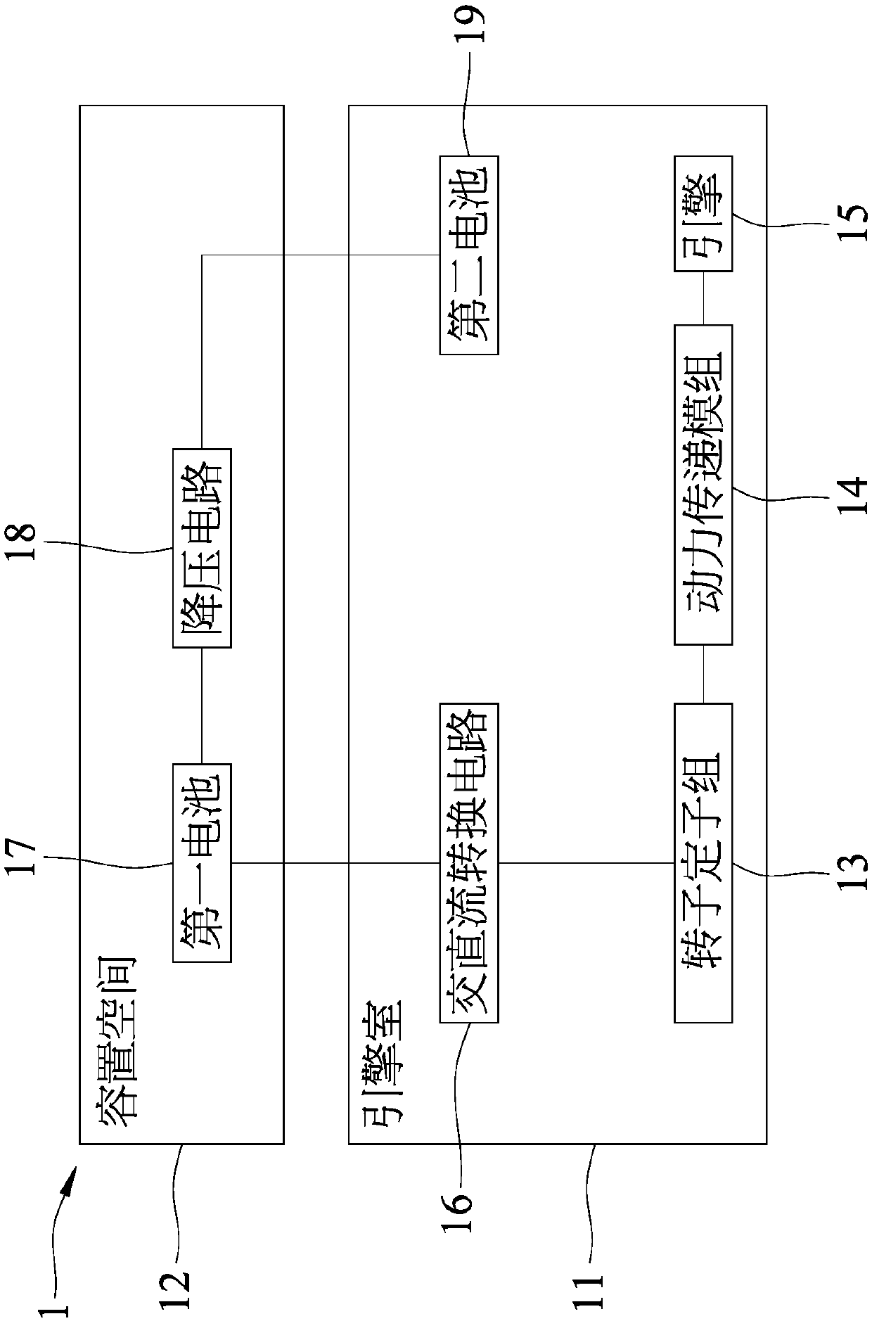
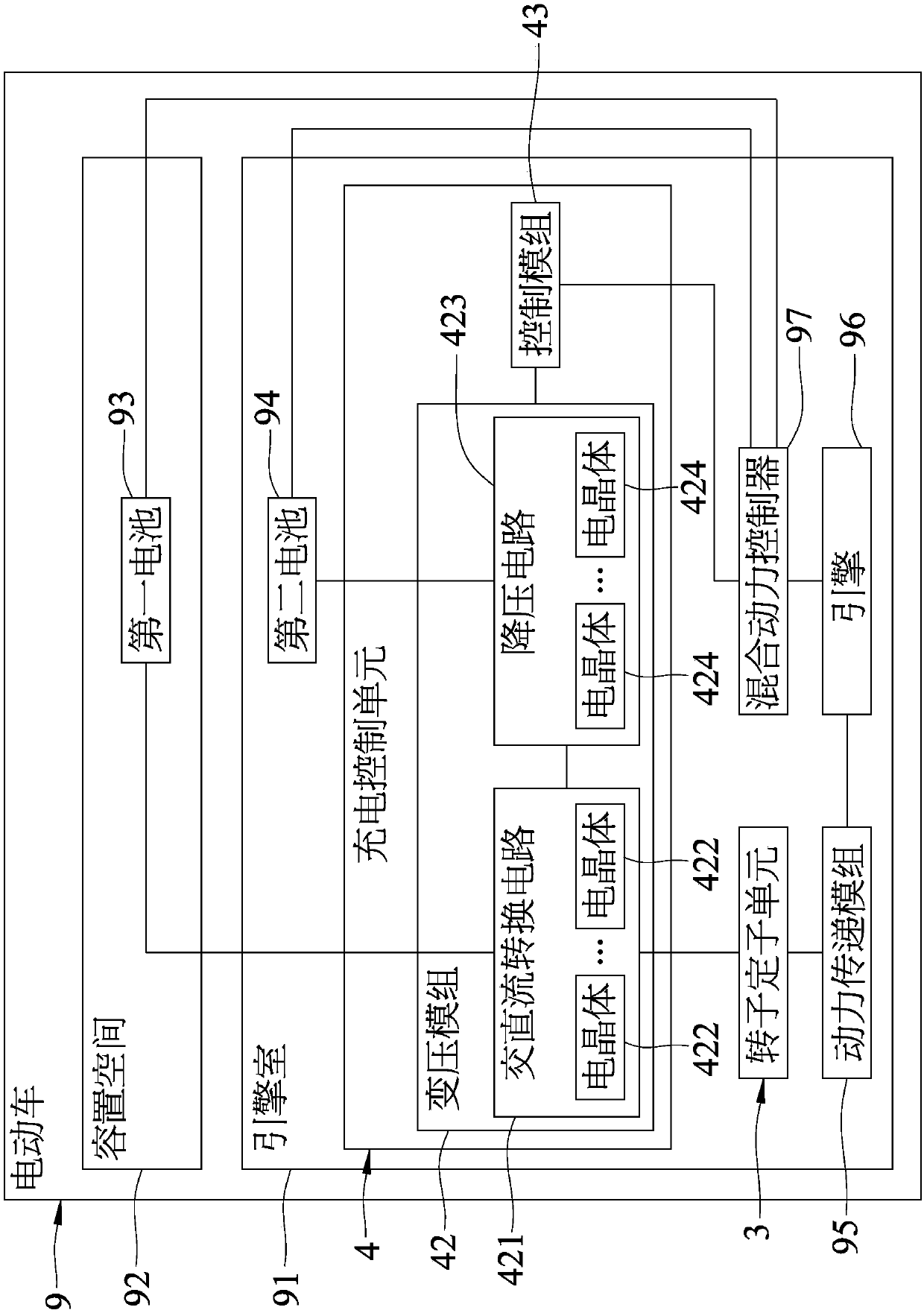
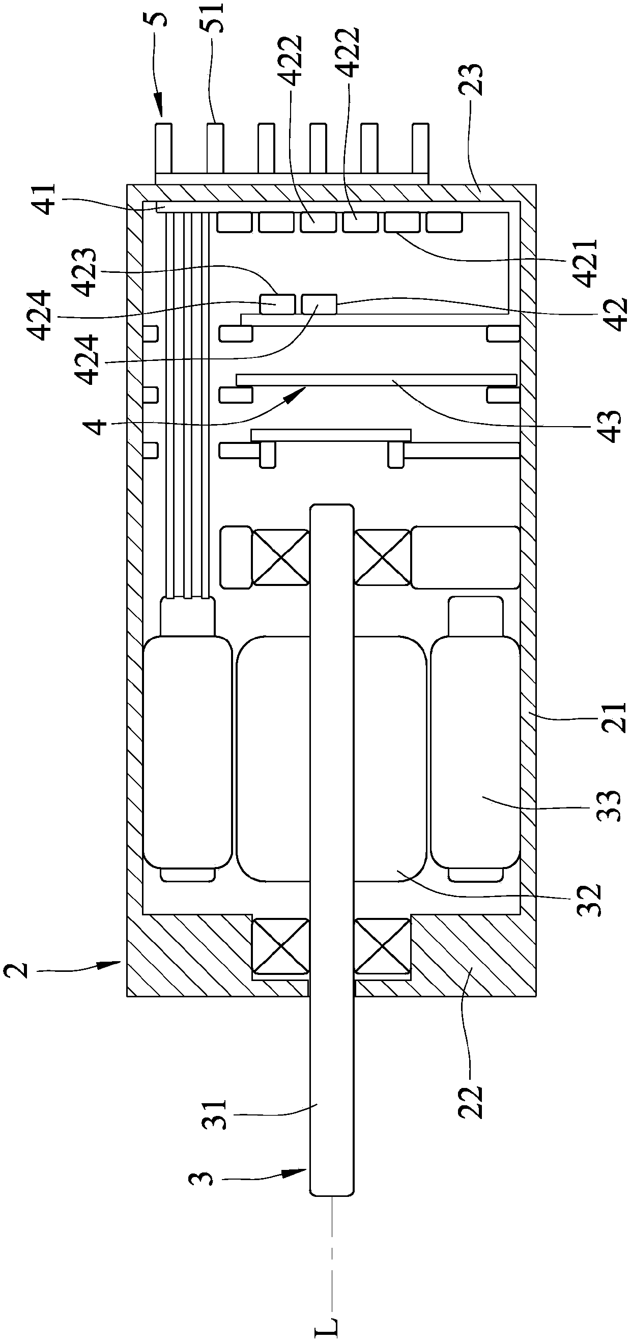
[0027] refer to figure 2 , 3 , a first embodiment of the vehicle motor with a built-in charging control function of the present invention is used for an electric vehicle 9, and the electric vehicle 9 includes an engine compartment 91 located at the front side, an accommodating space 92 located at the rear side, A first battery 93 storing a first DC voltage, a second battery 94 storing a second DC voltage lower than the first DC voltage, and a power transmission linking multiple wheels (not shown) module 95 , an engine 96 linked to the power transmission module 95 , and a hybrid controller 97 electrically connected to the first battery 93 , the second battery 94 and the engine 96 .

[0028] The first battery 93 is s...


PUM


Abstract

A vehicle motor with a charging control function comprises a metal casing unit, a rotor and stator unit, a charging control unit, and a heat radiation unit. The rotor and stator unit is accommodated in the metal casing unit, and linked to a power transmission module; the charging control unit includes a high heat conduction substrate arranged in the metal casing unit, a transformation module positioned in the metal casing unit and on the high heat conduction substrate and electrically connected with the rotor and stator unit and first and second batteries, and a control module arranged in themetal casing unit and electrically connected with the transformation module; and the heat radiation unit is arranged in the metal casing unit, and can simplify a transmission line. The transformationmodule and the rotor and stator unit share a heat radiation system, and thus, the production and manufacture cost can be reduced effectively, and the occupied size is reduced.

Description

technical field [0001] The invention relates to a motor for a vehicle, in particular to a motor for a vehicle with a built-in charging control function. Background technique [0002] Generally speaking, the power source of vehicles is to use internal combustion engines and burn fossil fuels as energy sources. However, due to the gradual depletion of fossil energy sources and environmental pollution problems in recent years, hybrid vehicles that use some green energy have become the new favorite in the market. On the one hand It can save energy and reduce pollution on the other hand, and the most common one at present is a hybrid electric vehicle (HEV, Hybrid Electric Vehicle). [0003] HEVs can be divided into Mild Hybrid and Full Hybrid based on the configuration of the output power. The main difference is that the light fuel electric vehicle uses the internal combustion engine as the main power source, and the output of the motor is configured. The power is low, and it is...

Claims


Application Information

Patent Timeline
Patent Type & Authority Applications(China)
IPC IPC(8): H02K5/04H02K5/18
CPCY02T10/64
Inventor 蔡琮镒刘志明陈昱吉曾达文宋柏奇罗济峰刘啓宇黄安正林俊宏郑谕鸿陈昆赐
Owner CHINA MOTOR CORPORATION
Why Eureka
Try Eureka