A polymer micro-negative pressure pyrolysis method for waste tires

A waste tire and polymer technology, applied in the field of tire pyrolysis, can solve the problems that the effect of tire pyrolysis methods needs to be improved

Active Publication Date: 2021-08-31
福建澳林镁环保科技有限公司
View PDF6 Cites 0 Cited by
  • Summary
  • Abstract
  • Description
  • Claims
  • Application Information

AI Technical Summary

Problems solved by technology

[0004] The purpose of the present invention is to aim at the technical defects of the prior art, and provide a polymer micro-negative pressure pyrolysis method for waste tires, so as to solve the technical problem that the effect of the tire pyrolysis method in the prior art needs to be improved

Method used


Image

  • A polymer micro-negative pressure pyrolysis method for waste tires
  • A polymer micro-negative pressure pyrolysis method for waste tires
  • A polymer micro-negative pressure pyrolysis method for waste tires

Examples


Embodiment 1

[0035] A polymer micro negative pressure pyrolysis method for waste tires, the method comprises the following steps:

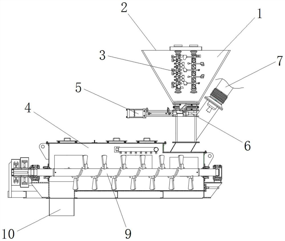
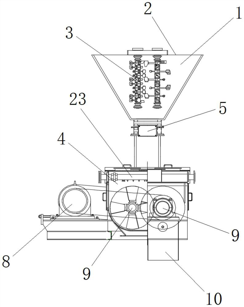
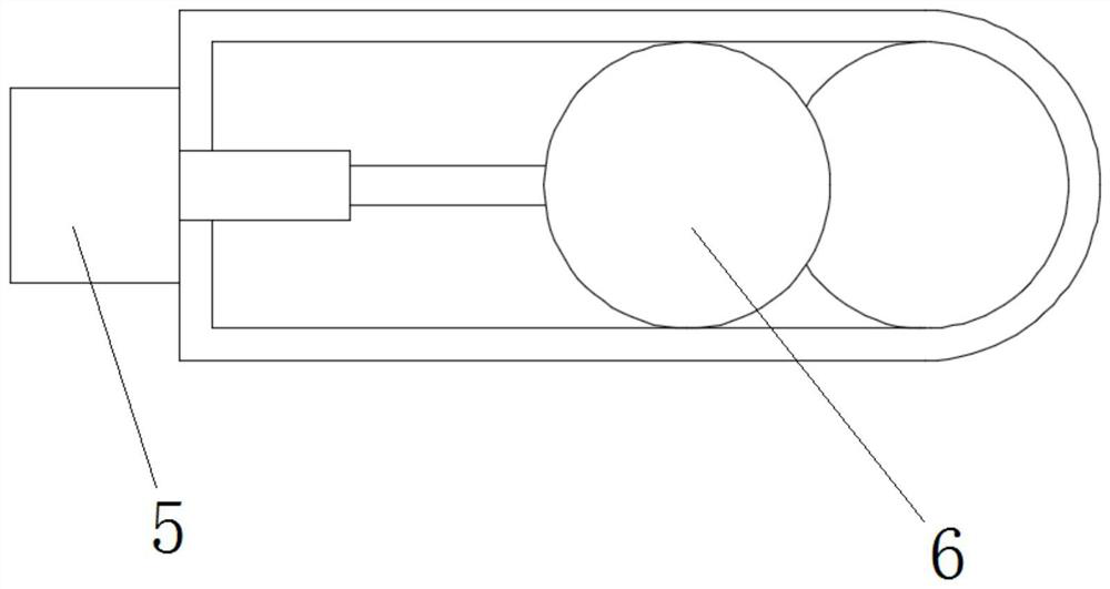
[0036]1) Put the block tires into the tank body 1 of the crushing mechanism, and at the same time use the electric push rod 5 to drive the sealing plate 6 to close the bottom end of the tank body 1, start the first rotating shaft 3, and crush the block tires to the particle size If it is less than 40 mesh, then open the sealing plate 6, input the crushed tire particles into the bin body 4, start the first motor 8 to drive the second rotating shaft 9 to rotate, further crush the material, and then discharge the material from the discharge port 10. out;

[0037] 2) Inject the unloaded material from the inline tube 14 of the reaction kettle into the kettle body 11, spread the material on the microporous plate 19, and lift the inline tube 14, so that the wide mouth 15 fits on the At the fixed ring 13, the air is pumped and decompressed from the port on the upper ...

Embodiment 2

[0044] A polymer micro negative pressure pyrolysis method for waste tires, the method comprises the following steps:

[0045] 1) Put the block tires into the tank body 1 of the crushing mechanism, and at the same time use the electric push rod 5 to drive the sealing plate 6 to close the bottom end of the tank body 1, start the first rotating shaft 3, and crush the block tires to the particle size If it is less than 40 mesh, then open the sealing plate 6, input the crushed tire particles into the bin body 4, start the first motor 8 to drive the second rotating shaft 9 to rotate, further crush the material, and then discharge the material from the discharge port 10. out;

[0046] 2) Inject the unloaded material from the inline tube 14 of the reaction kettle into the kettle body 11, spread the material on the microporous plate 19, and lift the inline tube 14, so that the wide mouth 15 fits on the At the fixed ring 13, the air is pumped and decompressed from the port on the upper...


PUM

PropertyMeasurementUnit
diameteraaaaaaaaaa

Abstract

The invention provides a polymer micro negative pressure pyrolysis method for waste tires. Specifically, in the present invention, block tires are directly pulverized in two stages, and the pulverized materials are injected into the microporous plate in the kettle body through the embedded tube of the reaction kettle, and then the kettle body is closed, and firstly, it is crushed at a low speed under a slight negative pressure condition. Raise the temperature to about 120°C, keep it for a period of time, then turn it into a deep negative pressure, and raise the temperature to 450°C at a relatively high speed, and carry out nitrogen protection, and then carry out continuous pyrolysis under reduced pressure conditions, and the pyrolyzed oil can be in Under pressure, it is discharged downward through the microporous plate, while the solid phase remains on the microporous plate. After drying and grinding, the existing metal wires in the tire exist in the form of particles or flakes, which can be removed by sieving . By applying the present invention, the whole process of tire crushing, pyrolysis and material collection can be completed in a consistent manner, and the stripping link of metal wires can be omitted, thereby obviously improving the continuity and process efficiency of the pyrolysis process.

Description

technical field [0001] The invention relates to the technical field of tire pyrolysis, in particular to a polymer micro-negative pressure pyrolysis method for waste tires. Background technique [0002] Waste tires have caused direct pollution to the environment, and countries all over the world are devoting themselves to research on the recycling of waste tires. Compared with waste tire treatment methods such as retreading, manufacturing rubber powder and reclaimed rubber, and incineration, the pyrolysis method has the characteristics of large waste tire treatment capacity, high efficiency and low environmental pollution, and is more in line with the recycling and harmlessness of waste treatment. Principles of minimization and reduction. In recent years, the pyrolysis treatment of waste tires has gradually developed from the laboratory stage to the large-scale stage, and the pyrolysis research of waste tires has gradually shifted from new process development and working con...

Claims


Application Information

Patent Timeline
Patent Type & Authority Patents(China)
IPC IPC(8): C10G1/10
Inventor 林利洪朱锡鑫
Owner 福建澳林镁环保科技有限公司
Why Eureka
Try Eureka