Tail gas aftertreatment device, selective catalytic reduction (SCR) front exhaust gas temperature control system and control method thereof

A technology of exhaust temperature and control system, which is applied in the direction of electronic control of exhaust gas treatment device, diagnosis device of exhaust gas treatment device, exhaust gas treatment, etc., can solve the problems of high cost, complicated structure of exhaust gas after-treatment device , to achieve the effect of low cost, simple structure and convenient installation

Active Publication Date: 2019-06-28
HENAN UNIV OF SCI & TECH
View PDF6 Cites 2 Cited by
  • Summary
  • Abstract
  • Description
  • Claims
  • Application Information

AI Technical Summary

Problems solved by technology

[0005] The purpose of the present invention is to provide a kind of exhaust gas temperature control system before SCR, to solve the technical problem that the exhaust gas temperature control system before SCR in the prior art is more complicated, the cost is higher; The purpose of the present invention is also to provide an exhaust gas Post-processing device to solve the technical problems of complex structure and high cost of exhaust gas post-processing device in the prior art; the purpose of the present invention is to provide a control method that can effectively control the exhaust temperature before SCR

Method used


Image

  • Tail gas aftertreatment device, selective catalytic reduction (SCR) front exhaust gas temperature control system and control method thereof
  • Tail gas aftertreatment device, selective catalytic reduction (SCR) front exhaust gas temperature control system and control method thereof
  • Tail gas aftertreatment device, selective catalytic reduction (SCR) front exhaust gas temperature control system and control method thereof

Examples


specific Embodiment

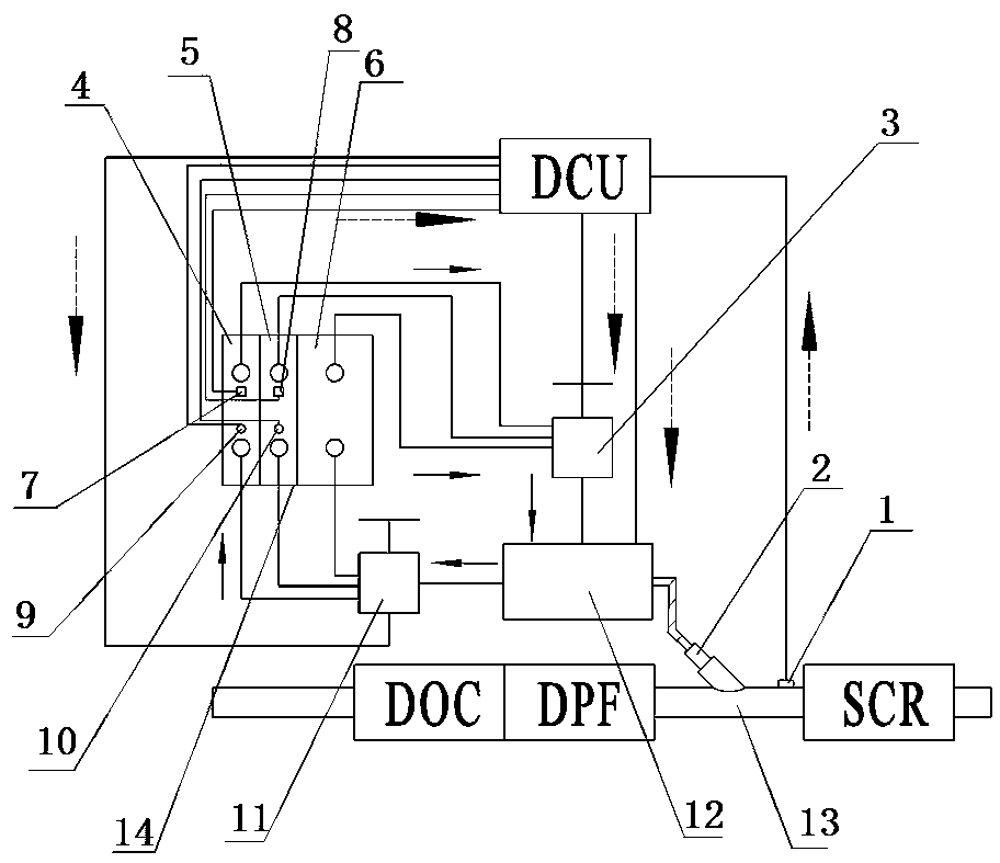
[0055] like figure 1 As shown, the exhaust temperature control system before the SCR includes a controller and a cooling channel 13 for connecting the DPF and the SCR. The controller includes a urea metering control unit (DCU); the cooling channel 13 is provided with installation holes for assembling urea injection Device 2. When the urea injector 2 is installed, its injection port extends into the inside of the cooling channel 13, and the joint between the urea injector 2 and the cooling channel 13 is provided with a gasket to seal the joint to prevent exhaust gas from leaking out. The end of the cooling channel 13 is used to connect the SCR, and the exhaust temperature sensor 1 is installed on the part between the connection of the urea injector 2 and the end of the cooling channel 13, and the urea metering control unit (DCU) can accept the exhaust temperature sensor 1 detected temperature signal.

[0056] The exhaust temperature control system before the SCR also includes...


PUM


Abstract

The invention relates to a tail gas aftertreatment device, a selective catalytic reduction (SCR) front exhaust gas temperature control system and a control method thereof. The SCR front exhaust gas temperature control system comprises a urea storage device, a urea pump, a urea supply control valve, a urea injector, an exhaust gas temperature sensor and a controller, and further comprises a coolingchannel used for connecting DPF with SCR and allowing tail gas to pass through; the urea ejector communicates with the cooling channel, the urea pump is connected with the urea storage device and theurea ejector and is connected with the controller in a controlled mode, and the urea storage device comprises a non-thermal regeneration urea storage chamber used for storing a urea solution used during non-DPF thermal regeneration and a thermal regeneration urea storage chamber used for storing a urea solution used during DPF thermal regeneration; and the concentration of the urea solution stored by the thermal regeneration urea storage chamber is lower than that of the urea solution used during non-DPF thermal regeneration. With the technical scheme, the technical problems of high complexity and high cost of an SCR front exhaust gas temperature control system in the prior art are solved.

Description

technical field [0001] The invention relates to the technical field of exhaust gas post-treatment of internal combustion engines, in particular to an exhaust gas post-processing device, an exhaust gas temperature control system before SCR and a control method thereof. Background technique [0002] There are two types of purification of diesel engine exhaust: organic internal purification and exhaust post-treatment. The after-treatment devices of diesel engines include DOC (oxidation catalytic converter), DPF (particulate filter), SCR (selective catalytic reduction technology), etc., which in turn In series in the exhaust system of the diesel engine. Among them, DPF is used to reduce engine particulate (PM) emissions. After the DPF has been used for a period of time, the particles adhere to the surface of the DPF, which affects the exhaust flow, increases fuel consumption, and deteriorates the economy of the diesel engine. At this time, it is necessary to remove the PM accum...

Claims


Application Information

Patent Timeline
Patent Type & Authority Applications(China)
IPC IPC(8): F01N3/20F01N11/00F01N3/04F01N3/023F01N13/00
CPCY02T10/12Y02T10/40
Inventor 李民刘春晓刘建新杜慧勇王站成苗家轩徐斌
Owner HENAN UNIV OF SCI & TECH
Why Eureka
Try Eureka