
Conical ring friction coefficient detection device and method of synchronizer

A friction coefficient and detection device technology, which is applied in the field of synchronizer cone ring friction coefficient detection devices, can solve the problems of inability to measure the synchronizer cone ring friction coefficient, lack of testing equipment, and high production costs, and achieves a high degree of true reduction and a simple structure. , the effect of low production cost

Pending Publication Date: 2019-06-28
SHAANXI FAST AUTO DRIVE GROUP CO LTD
View PDF0 Cites 0 Cited by
  • Summary
  • Abstract
  • Description
  • Claims
  • Application Information

AI Technical Summary

Problems solved by technology

[0003] At present, there is no special test equipment for testing the friction coefficient of synchronizers in China. Most manufacturers use friction material test blocks to measure the friction coefficient, and cannot measure the friction coefficient of the synchronizer cone ring. The measurement results have certain reference significance, but It is not accurate; while foreign equipment of this type has complex structures and high production costs

Method used


Image

  • Conical ring friction coefficient detection device and method of synchronizer
  • Conical ring friction coefficient detection device and method of synchronizer
  • Conical ring friction coefficient detection device and method of synchronizer

Examples


Embodiment Construction

[0034] Below in conjunction with accompanying drawing and specific embodiment content of the present invention is described in further detail:

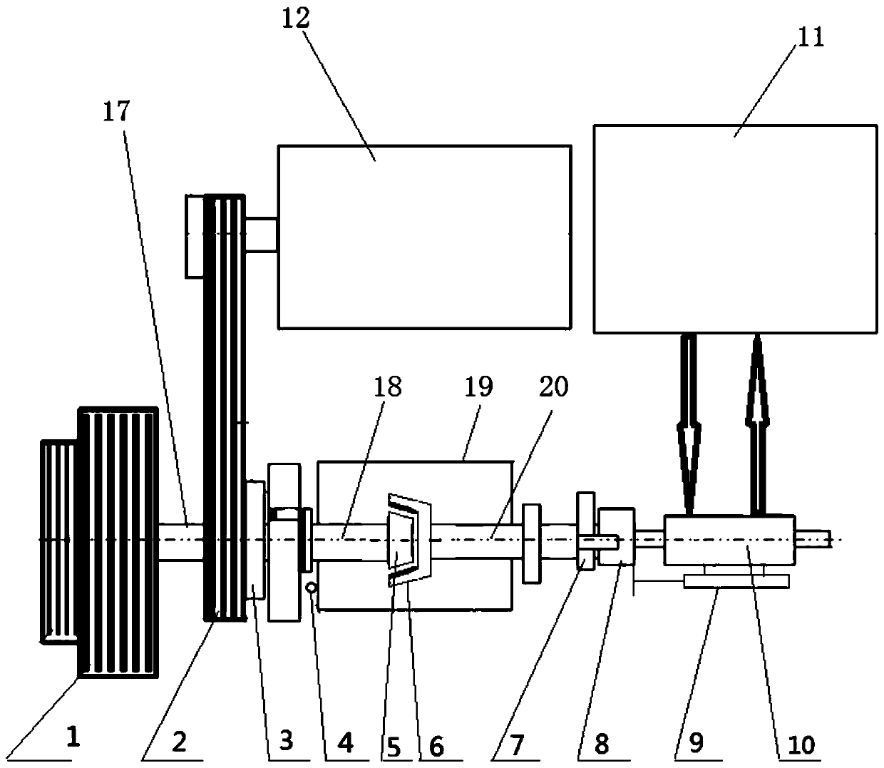
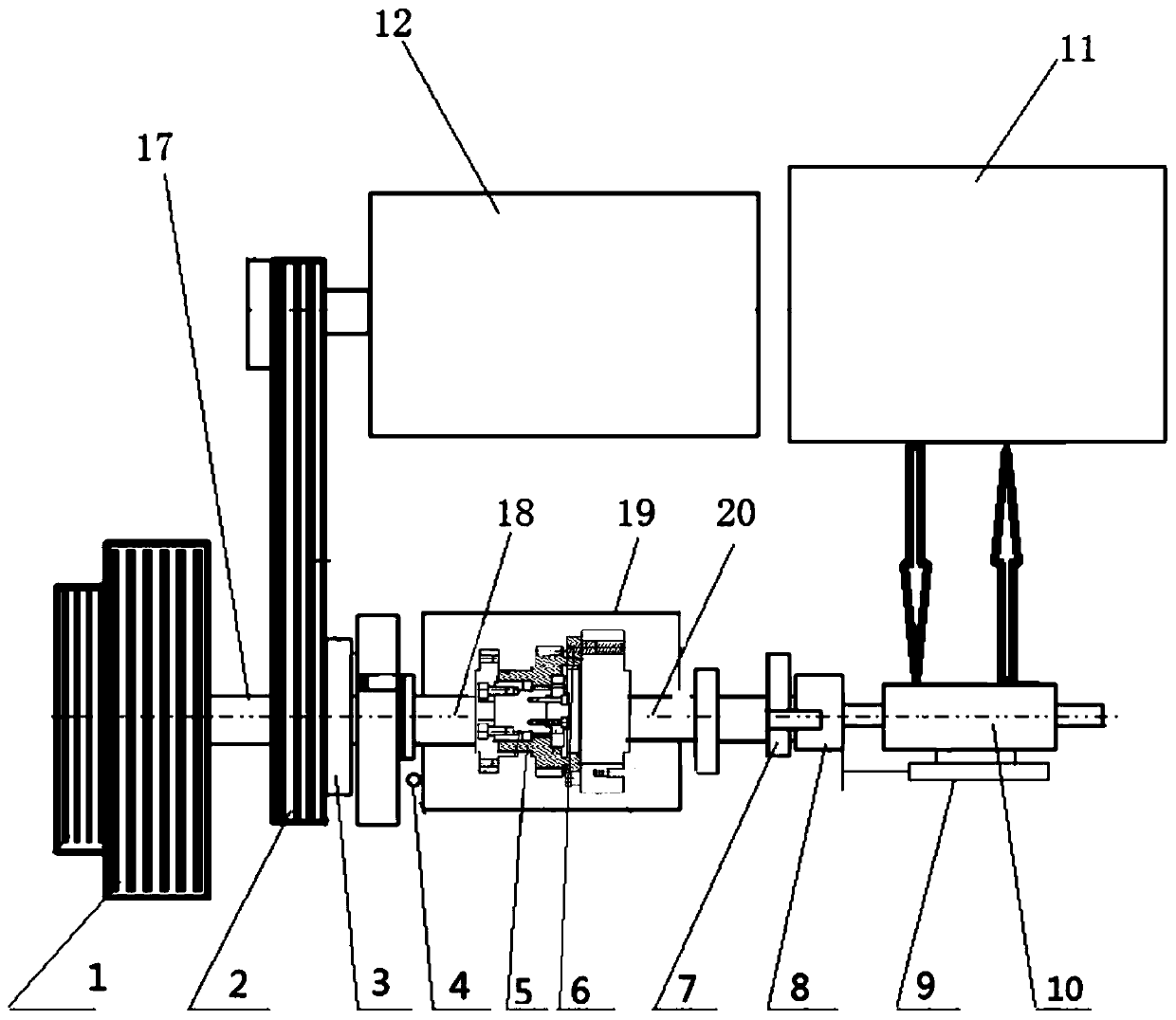
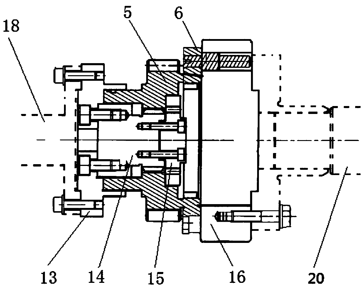
[0035] Such as Figure 1-Figure 3 As shown, a synchronizer cone ring friction coefficient detection device includes an AC motor, an inertial body 1, an electromagnetic clutch 3, a hydraulic power unit, a driving shaft 17, a rotating shaft 18, a driven shaft 20, a speed sensor 4, a torque sensor 7, A force sensor 8 and a displacement sensor 9; the hydraulic power device includes a connected hydraulic source 11 and a hydraulic actuator 10.

[0036] Wherein, the driving shaft 17, the rotating shaft 18 and the driven shaft 20 are arranged coaxially in sequence; the electromagnetic clutch 3 is arranged between the driving shaft 17 and the rotating shaft 18; the inertia body 1 is arranged on the driving shaft 17, and the AC motor is driven by the power transmission assembly The inertial body 1 rotates, and the power transmission assembly i...


PUM


Abstract

The invention provides a conical ring friction coefficient detection device and method of a synchronizer, and aims at filling blank in research on synchronizer friction material in the industry, and providing theoretical data for designers. The detection device comprises a driver, an inertia body, an electromagnetic clutch, a hydraulic power unit, a driving shaft, a rotating shaft, a driven shaft,a rotating speed sensor, a torque sensor, a force sensor and a displacement sensor; the driving shaft, the rotating shaft and the driven shaft are arranged coaxially; the electromagnetic clutch is arranged between the driving shaft and the rotating shaft; the driver drives the inertia body to rotate via a power transmission assembly, and the inertia body is arranged on the driving shaft; the electromagnetic clutch drives the driving end to rotate via the rotating shaft; the driven end is arranged in the end close to the driving end of the driven shaft, and is driven by the hydraulic power device to make axial movement; the rotating speed sensor is arranged on the rotating shaft; one end of the displacement sensor is connected with the driven shaft, and the other end of the displacement sensor is fixedly arranged; and the torque sensor and force sensor are arranged on the rotating shaft or driven shaft.

Description

technical field [0001] The invention belongs to the technical equipment of an automobile component test bench, and in particular relates to a detection device and a detection method for the friction coefficient of a synchronizer cone ring. Background technique [0002] The synchronizer is one of the most important components in the gearbox of cars and trucks. The evaluation of the synchronizer is mainly reflected in the synchronization performance index. In the synchronizer system, the efficient friction layer will play a decisive role in improving the performance of the synchronizer The friction coefficient between the friction layers is an important indicator to determine the performance of the synchronizer. [0003] At present, there is no special test equipment for testing the friction coefficient of synchronizers in China. Most manufacturers use friction material test blocks to measure the friction coefficient, and cannot measure the friction coefficient of the synchron...

Claims


Application Information

Patent Timeline
Patent Type & Authority Applications(China)
IPC IPC(8): G01M13/02G01M13/025G01N19/02
Inventor 韩芃芃
Owner SHAANXI FAST AUTO DRIVE GROUP CO LTD
Learn More