

Transmission line inspection robot based on UAV platform
A technology for inspection robots and transmission lines, which is applied to overhead lines/cable equipment, shutdown devices, etc., and can solve problems such as single working mode and low efficiency
- Summary
- Abstract
- Description
- Claims
- Application Information
AI Technical Summary
Problems solved by technology
Method used
Image

Examples
Embodiment 1
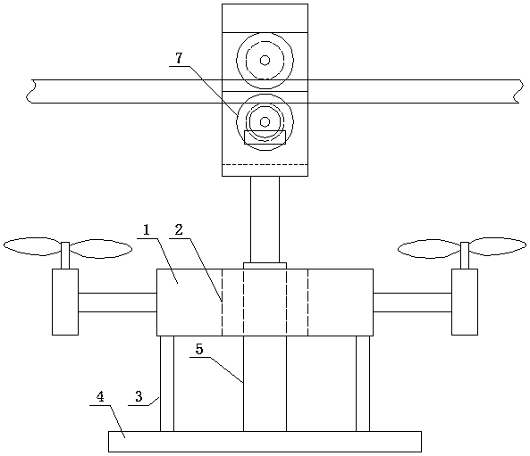
[0033] Such as figure 1 and figure 2 As shown, a transmission line inspection robot based on an unmanned aerial vehicle platform includes a four-rotor unmanned aerial vehicle body 1, and the middle part of the four-rotor unmanned aerial vehicle body 1 has a channel 2 that runs through up and down, and the four-rotor unmanned aerial vehicle The bottom of the main body 1 is suspended with a bearing plate 4 through a plurality of support rods 3, and a power transmission line running mechanism is arranged on the bearing plate 4.
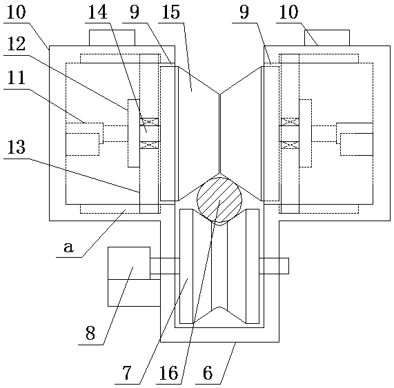
[0034] The transmission line running mechanism includes a vertical electric telescopic rod 5 arranged on the bearing plate 4, the upper end of the vertical electric telescopic rod 5 protrudes from the passage 2, and the upper end of the vertical electric telescopic rod 5 is set The U-shaped driving wheel frame 6 with the opening facing upwards, the driving roller 7 is rotated in the U-shaped driving wheel frame 6, and the driving roller 7 is driven by ...
Embodiment 2
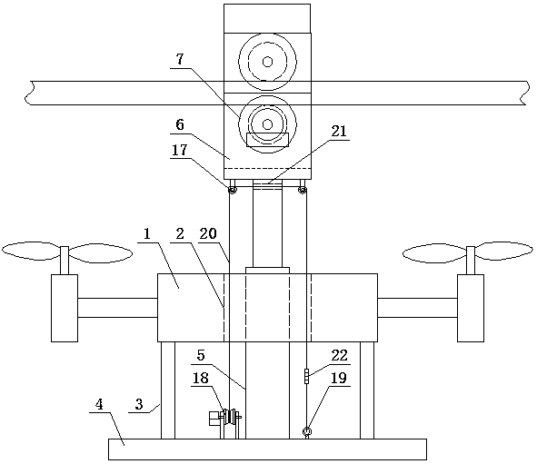
[0038] Such as image 3 As shown, the difference from Embodiment 1 is that a pair of fixed pulleys 17 are arranged symmetrically on the bottom of the U-shaped driving wheel frame 6 and on both sides of the vertical electric telescopic rod 5, and on the bearing plate 4 and are located An electric wire reel 18 is arranged directly below one fixed pulley 17, a fixed ring 19 is arranged on the bearing plate 4 and directly below the other fixed pulley 17, and a stay wire 20 is wound on the electric wire reel 18. The end of the stay wire 20 passes through a fixed pulley 17 directly above the electric reel 18, a threading hole 21 provided on the vertical electric telescopic rod 5, and a threading hole 21 located directly above the fixed ring 19. A fixed pulley 17 above is fixed on the fixed ring 19 by a tension sensor 22, and the tension sensor 22 and the electric reel 18 are all automatically controlled by the flight control system in the quadrotor UAV body 1 .
[0039] In this em...
Embodiment 3
[0041] Such as Figure 4 As shown, the difference between it and Embodiment 2 is that: the opposite facades on the two truncated cones 15 realize the butt joint through the insertion rod structure b.
[0042] In this embodiment, in order to make the two truncated cones lean against each other under the telescopic action of the respective horizontal electric telescopic rods to form a stable and complete driven roller, the two truncated cones are inserted between the opposite facades Hole inserting rod structure realizes the connection, the jack inserting rod structure can adopt the jack hole on one of the truncated cones and set the inserting rod matching the jack on the other truncated cone, of course, it can also be used in one of the truncated cones A plunger is arranged on the top, and a socket matched with the plunger is arranged on the other conical truncated cone.
PUM
 Abstract
Description
Claims
Application Information