Transversely uniform microwave oven
A microwave heating furnace and uniform technology, applied in the field of microwave ovens, can solve problems such as difficult calculation, complicated measurement, and exceeding the complexity of microwave heating problems.
- Summary
- Abstract
- Description
- Claims
- Application Information
AI Technical Summary
Problems solved by technology
Method used
Image
Examples
Embodiment 1
[0091] Such as figure 1 and 2 .
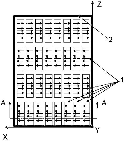
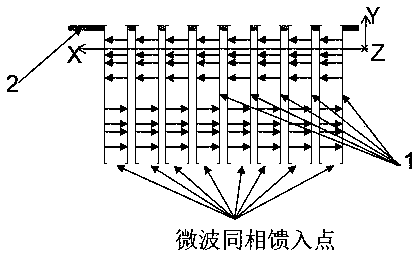
[0092] A horizontally uniform microwave heating furnace includes a heating chamber and a radiation array. The radiation array includes 4 rows of radiators 1 along the Z axis and 8 columns of radiators 1 along the X axis. The radiation array radiates microwave energy to the heating chamber 3 through the floor 2 .
[0093] The radiators 1 on the radiation array are evenly distributed along the X direction and along the Z direction. At the same time, the microwaves radiated by all radiators 1 on the radiation array are coherent waves. The microwaves radiated by all the radiators 1 arranged in the same row along the X-axis on the radiation array have the same amplitude and the same phase. The microwaves radiated by any two adjacent radiators 1 belonging to the same row on the same radiation array along the Z axis have the same amplitude and opposite phases.
[0094] The microwaves radiated by all the radiators 1 on the radiation array have a...
Embodiment 2
[0098] Such as image 3 and 4 shown.
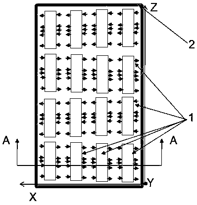
[0099] Compared with Embodiment 1, the only difference is that the radiator 1 is a patch antenna. The antenna mainly includes a metal sheet on the surface of the dielectric material sheet supported by a dielectric material sheet and a microwave excitation structure on the other surface of the dielectric material sheet opposite to the metal sheet. The distance between the centers of adjacent patch antennas along the Z axis is 3 / 5-9 / 10 of the wavelength of the working microwave free space. The distance between the centers of adjacent patch antennas along the X axis is less than half of the wavelength of the working microwave free space. The shape of the patch antenna is rectangular.
[0100] Different from the rectangular waveguide propagating the TE10 mode in Example 1, the patch antenna here radiates microwave energy through its two long sides perpendicular to the X axis.
Embodiment 3
[0102] Such as Figure 5 and 6 shown.
[0103] Compared with Embodiment 1, the only difference is that the radiator 1 is a coaxial antenna. The coaxial antenna here uses a coaxial line to feed microwave energy. The outer conductor of the coaxial line and the medium between the outer conductor and the inner conductor are cut off, but its inner conductor protrudes into free space. A metal disc is attached to the top of the inner conductor.
[0104] The distance between the centers of the adjacent coaxial antennas adjacent along the X axis and adjacent along the Z axis is 3 / 5~9 / 10 of the wavelength of the working microwave free space. The component of the electric field in the X-axis direction of the microwaves radiated by the radiators 1 arranged in the same column along the Z-axis on the center line of each radiator 1 along the X-axis is zero. The microwaves radiated by the radiators 1 arranged in the same row along the X axis on the same radiation array have a zero compon...
PUM
 Abstract
Description
Claims
Application Information
 - R&D
- Intellectual Property
- Life Sciences
- Materials
- Tech Scout
- Unparalleled Data Quality
- Higher Quality Content
- 60% Fewer Hallucinations
Browse by: Latest US Patents, China's latest patents, Technical Efficacy Thesaurus, Application Domain, Technology Topic, Popular Technical Reports.
© 2025 PatSnap. All rights reserved.Legal|Privacy policy|Modern Slavery Act Transparency Statement|Sitemap|About US| Contact US: help@patsnap.com


