Dynamic control method for refining ultra-low carbon steel through RH CO2 spraying

A dynamic control, ultra-low carbon steel technology, applied in the field of steelmaking technology, can solve the problems of large consumption of deoxidized alloys, easy peroxidation of molten steel, and high production costs, and can shorten the refining rhythm, improve the quality of molten steel, and improve the quality of molten steel. quality effect

Active Publication Date: 2019-07-02
UNIV OF SCI & TECH BEIJING
View PDF3 Cites 19 Cited by
  • Summary
  • Abstract
  • Description
  • Claims
  • Application Information

AI Technical Summary

Problems solved by technology

[0006] In view of the above problems, the present invention proposes a RH injection CO 2 The dynamic control method for refining ultra-low carbon steel solves the technical problems of easy peroxidation of molten steel, large consumption of deoxidized alloy, and high production cost in the existing RH refining process

Method used


Image

  • Dynamic control method for refining ultra-low carbon steel through RH CO2 spraying
  • Dynamic control method for refining ultra-low carbon steel through RH CO2 spraying

Examples


Embodiment 1

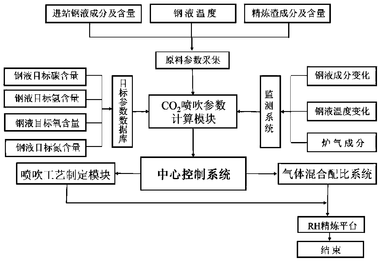
[0020] Embodiment 1: the present invention is applied in the 150tRH refining process, and the top blowing gas is O 2 +CO 2 , the lifting gas is Ar+CO 2 , the deoxidizer adopts aluminum block alloy, and the alloy yield is 80%. Specific steps are as follows:

[0021] 1): Quickly measure the carbon content of molten steel in RH through the RH inbound molten steel composition data acquisition system [%C] 0 =0.038%, and transmit it to the central control system, and formulate the operation process of the forced decarburization period according to the target composition data of molten steel.

[0022] 2): During the forced decarburization period, according to the operation process formulated in step 1, under the ultimate vacuum, use top blown O 2 +CO 2 Carry out forced decarburization with Ar+CO 2 In order to enhance the circulating stirring of molten pool by lifting gas, predict the carbon content of molten steel at the end of decarburization [%C] f , and at the end of decarbur...

Embodiment 2

[0027] Embodiment 2: the present invention is applied in the 300t RH refining process, and the top blowing gas is O 2 +CO 2 , the lifting gas is Ar+CO 2 , the deoxidizer adopts aluminum block alloy, and the alloy yield is 75%. Specific steps are as follows:

[0028] 1): Quickly measure the carbon content of molten steel in RH through the RH inbound molten steel composition data acquisition system [%C] 0 =0.035%, and transmit it to the central control system, and formulate the operation process of the forced decarburization period according to the target composition data of molten steel.

[0029] 2): During the forced decarburization period, according to the operation process formulated in step 1, under the ultimate vacuum, use top blown O 2 +CO 2 Carry out forced decarburization with Ar+CO 2 In order to enhance the circulating stirring of molten pool by lifting gas, predict the carbon content of molten steel at the end of decarburization [%C] f , and at the end of decar...


PUM


Abstract

The invention belongs to the technical field of steelmaking, and particularly relates to a dynamic control method for refining ultra-low carbon steel through RH CO2 spraying. The dynamic control method is suitable for a 30-300 t RH ladle refining process. In the RH refining process, O2 and CO2 are adopted as top-blowing gases, Ar and CO2 are used as lifting gases; molten steel components in the refining process are predicted based on material conservation according to RH refining in-station molten steel component data, refining process furnace gas component data and vacuum equipment working conditions; the top blowing and lifting gas flow is dynamically adjusted according to requirements of target components of refined molten steel stage by stage; on the basis of strengthening the stirringeffect of the RH refining process, the nitrogen content in the molten steel is further reduced, and the quality of molten steel is improved; and meanwhile, excessive oxidation of the molten steel inthe RH decarbonization process is avoided, the consumption of a deoxidized alloy is reduced, and on the basis of reducing the consumption of Ar, the production cost is further reduced, and the refining period is shortened. As a result, the alloy consumption is reduced by 3%-8%, the RH refining period is shortened by 1-2 minutes, the denitrification amount is increased by (3-10)*10<-6>, and the quality of the molten steel is improved.

Description

technical field [0001] The invention relates to the technical field of steelmaking technology, in particular to an RH injection CO 2 A dynamic control method for refining ultra-low carbon steel. Background technique [0002] The RH vacuum degassing method has developed from dehydrogenation treatment in the 1950s to a refining method with multiple metallurgical functions such as dehydrogenation, deoxidation, decarburization, desulfurization, and dephosphorization. At present, RH has become the most widely used refining equipment outside the furnace in the world. It has achieved remarkable effects in improving the quality of molten steel and reducing costs, and is suitable for mass production of ultra-pure steel. Traditional RH refined with O 2 , Ar are top blowing and lifting gases respectively, which are used for decarburization and driving cycle of ultra-low carbon steel production to complete the task of molten steel refining. However, this method will cause a series o...

Claims


Application Information

Patent Timeline
Patent Type & Authority Applications(China)
IPC IPC(8): C21C7/10C21C7/072C21C7/06C21C7/068
CPCC21C7/06C21C7/068C21C7/072C21C7/10
Inventor 魏光升韩宝臣朱荣武文合冯超姜娟娟董建锋吕明吴学涛李伟峰胡绍岩董凯刘润藻朱长富周贺贺李强李明
Owner UNIV OF SCI & TECH BEIJING
Why Eureka
Try Eureka