
Method to reduce sludge generation in wastewater treatment systems

a wastewater treatment system and sludge technology, applied in the field of wastewater treatment systems, can solve the problems of reducing the phosphorus content of sludge, the most expensive process in the operation of wastewater treatment plants, and the microbial byproduct of biological wastewater treatment, so as to reduce the phosphorus conten

Active Publication Date: 2012-06-21
UNIV OF MASSACHUSETTS
View PDF17 Cites 23 Cited by
  • Summary
  • Abstract
  • Description
  • Claims
  • Application Information

AI Technical Summary

Benefits of technology

[0013]In some embodiments, the at least one output port is in fluid connection with an input port of a reactor in a main treatment stream of the wastewater treatment facility. In some embodiments, the at least one output port in fluid connection with an input port of a reactor in a main treatment stream of the wastewater treatment facility is in fluid connection with an aerobic reactor in the main treatment stream. In some embodiments, the at least one output port in fluid connection with an input port of a reactor in a main treatment stream of the wastewater treatment facility is in fluid connection with an anoxic reactor in the main treatment stream. In some embodiments, the anoxic reactor is configured to accept effluent from the tank reactor and in response thereto, to reduce a nitrogen content of an effluent of the wastewater treatment facility.
[0015]In some embodiments, the anaerobic reactor is configured to accept effluent from the tank reactor and in response thereto, to reduce a phosphorus content of an effluent of the wastewater treatment facility.

Problems solved by technology

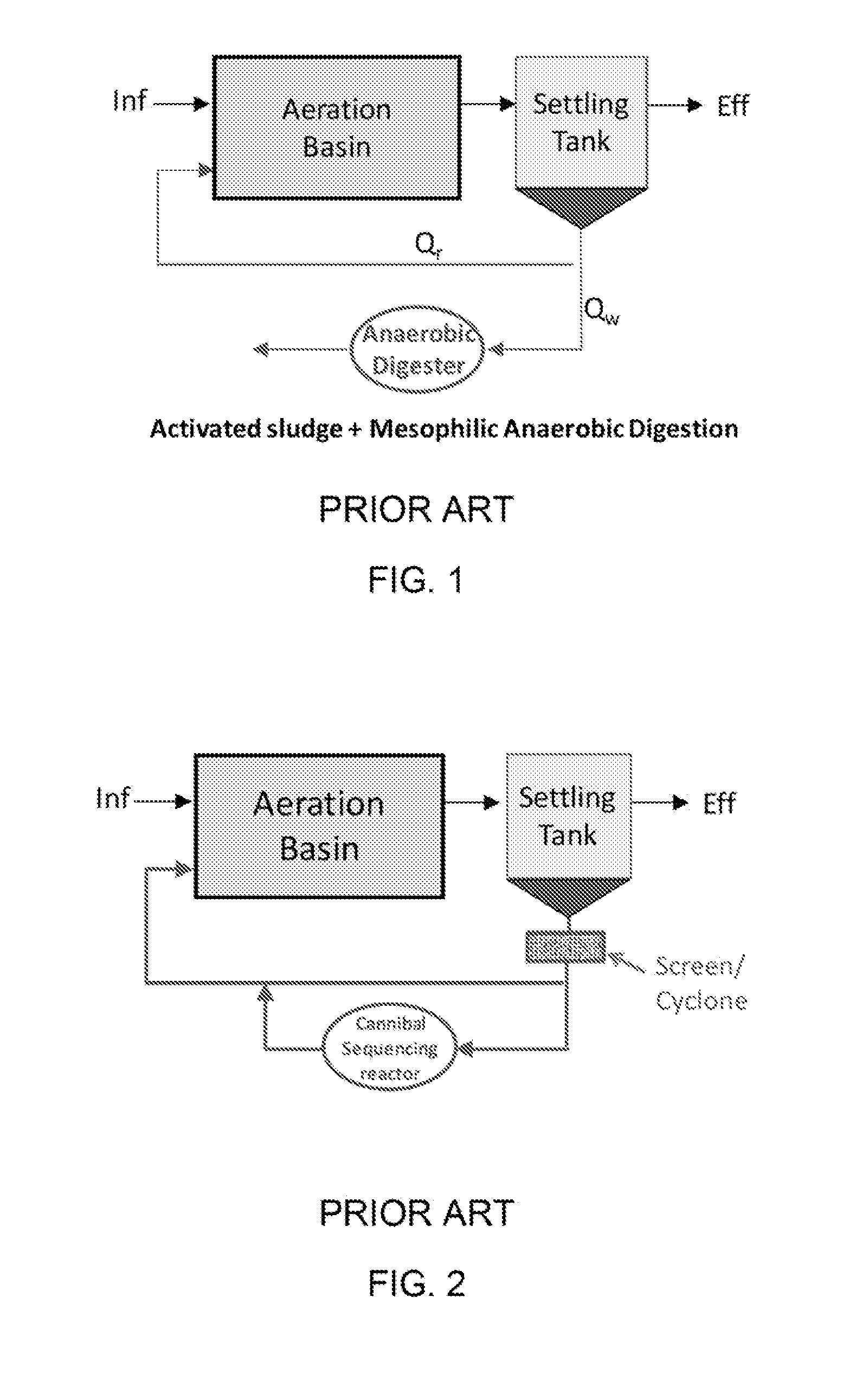
The treatment of sludge biomass, a microbial byproduct of biological wastewater treatment, is the most costly process in operation of wastewater treatment plant.
All these steps require much energy and efforts to meet the regulations.
The digested sludges, however, still require conditioning, dewatering, and final disposal.
Conventional sludge treatments such as incineration or heat drying of sludge face significant challenges due to increased fuel prices and elevated concerns in air pollution.

Method used


Image

  • Method to reduce sludge generation in wastewater treatment systems
  • Method to reduce sludge generation in wastewater treatment systems
  • Method to reduce sludge generation in wastewater treatment systems

Examples


Embodiment Construction

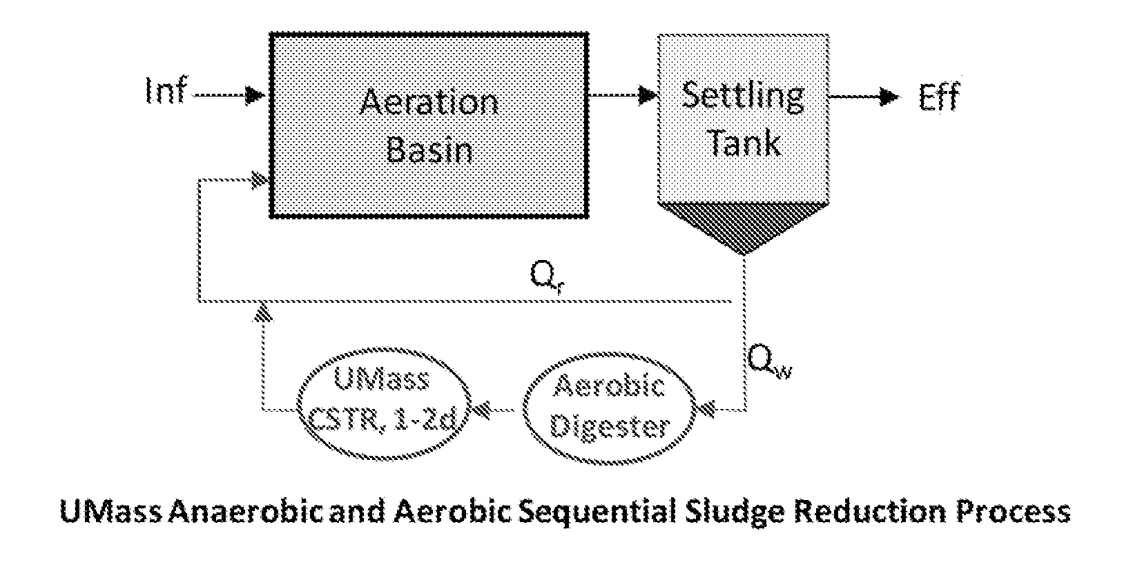
[0042]The invention relates to the technology for reducing sludge generation in wastewater treatment plants. In one embodiment, the systems and methods of the invention leads to extremely low sludge yield, thus allowing significantly reduced sludge wasting from the wastewater treatment systems. The systems and methods of the invention also permit reduction of nitrogen and phosphorous in effluent without the addition of external organic carbon or without requirement of a complex reactor design such as pre-denitrification with mixed liquor recirculation. The systems and methods of the invention also provide for generation of hydrogen from the anaerobic bioreactor which can be used as an energy source for the facility.

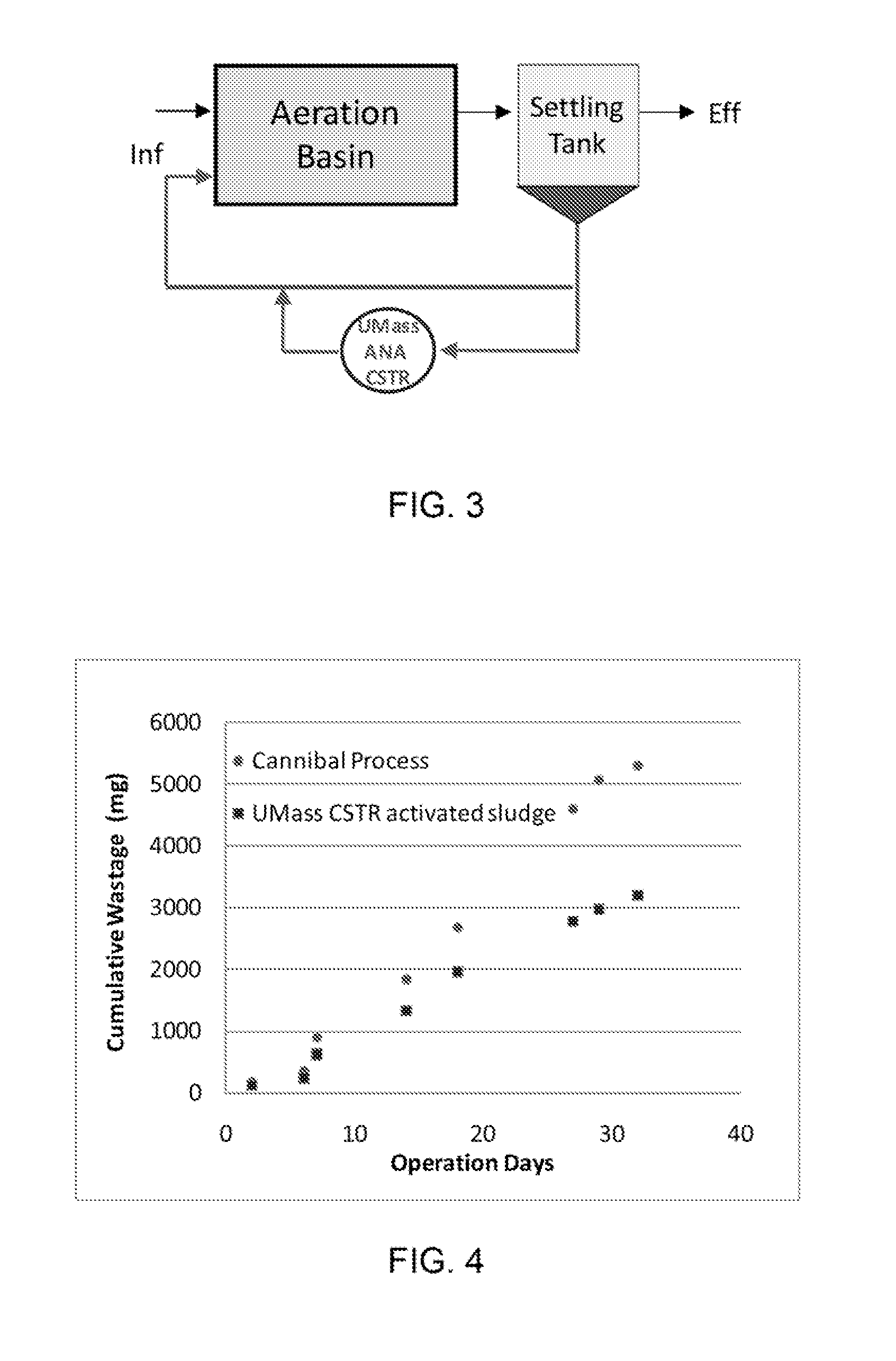
[0043]In another aspect, the systems and methods of the invention feature an external anaerobic hydrolysis and fermentation bioreactor that treats excess sludge and returns it back to the main wastewater reaction basin. The tank reactor is operationally within the loop of...


PUM

PropertyMeasurementUnit
Temperatureaaaaaaaaaa
Contentaaaaaaaaaa
Timeaaaaaaaaaa

Abstract

The systems and methods described provide for reducing sludge generation, and thus sludge wasting and handling, by including an anaerobic completely stirred tank reactor (CSTR) as a bioreactor in a side-stream. The CSTR provides a significant simplification of side-stream treatment design, enhanced sludge minimization, and enhanced removal of nitrogen and phosphorous without the need to add organic carbon. The described systems and methods provide generation of biogas including both hydrogen and methane from the activated sludge system. The described systems and methods avoid complex reactor designs for nutrient removal.

Description

CROSS-REFERENCE TO RELATED APPLICATIONS[0001]This application claims priority to and the benefit of co-pending U.S. provisional patent application Ser. No. 61 / 187,403, filed Jun. 16, 2009 which application is incorporated herein by reference in its entirety.FIELD OF THE INVENTION[0002]The invention relates to systems and methods for wastewater treatment in general and particularly to sludge treatment systems and methods that enable minimized sludge generation, reduction of effluent nutrients, and production of bio-hydrogen by employing a single side-stream anaerobic completely-stirred-tank reactor (CSTR).BACKGROUND OF THE INVENTION[0003]Wastewater treatment plants (WWTPs) are ubiquitous. The treatment of sludge biomass, a microbial byproduct of biological wastewater treatment, is the most costly process in operation of wastewater treatment plant. The vast majority of WWTPs use an activated sludge process. Wastewater is broken down by microbes in an aeration basin. This leads to grow...

Claims


Application Information

Patent Timeline
IPC IPC(8): C02F3/30C02F3/28B01D21/02
CPCC02F1/302C02F1/34C02F1/36C02F1/46Y02E50/343C02F3/2813C02F3/308C02F11/18C02F3/1221Y02E50/30Y02W10/10
Inventor PARK, CHULCHON, DONG-HYUN
Owner UNIV OF MASSACHUSETTS
Learn More