Turbocharger lubricating oil return device

A technology of turbocharger and lubricating oil, applied in the direction of machine/engine, mechanical equipment, engine components, etc., can solve the problems of limited oil and gas separation effect, poor oil return, insufficient oil return pressure, etc., to reduce oil consumption , The effect of reducing maintenance costs and reducing failure rates

Active Publication Date: 2020-08-11
DONGFENG COMML VEHICLE CO LTD
View PDF6 Cites 0 Cited by
  • Summary
  • Abstract
  • Description
  • Claims
  • Application Information

AI Technical Summary

Problems solved by technology

But this turbocharger oil return method has the following disadvantages: one, it is not suitable for engines with a small difference in height between the oil return port of the turbocharger and the oil return port of the engine body
If the position of the oil return port of the engine body is above the liquid level of the oil pan, but the height drop is small and the oil return pressure is insufficient, then when the car goes uphill or downhill, the engine will lean forward or backward, and when the height drop is further reduced, It will lead to poor oil return or oil pouring into the supercharger, causing oil leakage in the supercharger
2. It is especially not suitable for engines where the oil return port of the engine body is below the oil level of the oil pan
Although this structure increases the oil-gas separation function, so that the lubricating oil can return to the oil smoothly, in the whole process, there are two defects in the oil return pipe of the turbocharger: on the one hand, the pressure in the respirator 8 enters with the air inlet 87 The high-temperature lubricating oil changes, and the oil-gas separation effect is very limited. The blow-by gas will enter the crankcase through the supercharger oil return pipe, resulting in an increase in the pressure in the crankcase. In cold weather, a good lubrication cycle has not been established, and the lubricating oil in the turbocharger has flowed out due to gravity, which leads to the semi-dry friction state of the turbocharger, which will cause great damage to the turbocharger

Method used


Image

  • Turbocharger lubricating oil return device
  • Turbocharger lubricating oil return device

Examples


Embodiment Construction

[0020] The present invention will be further described in detail below in conjunction with the accompanying drawings and specific embodiments.

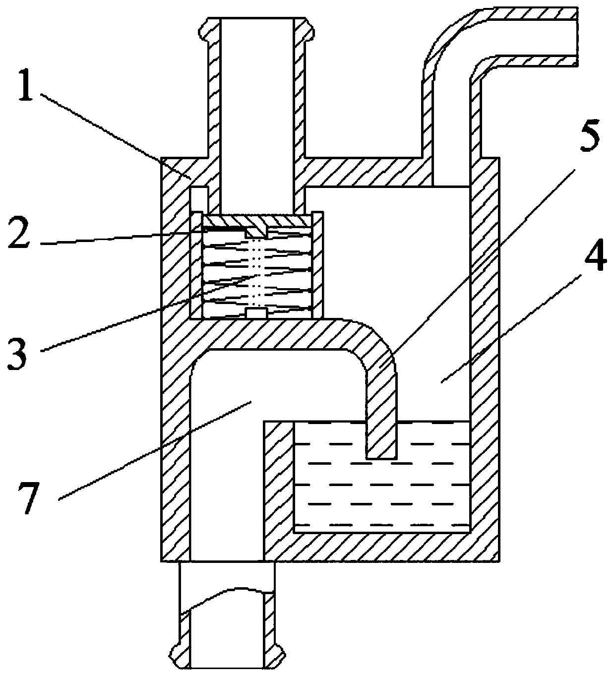
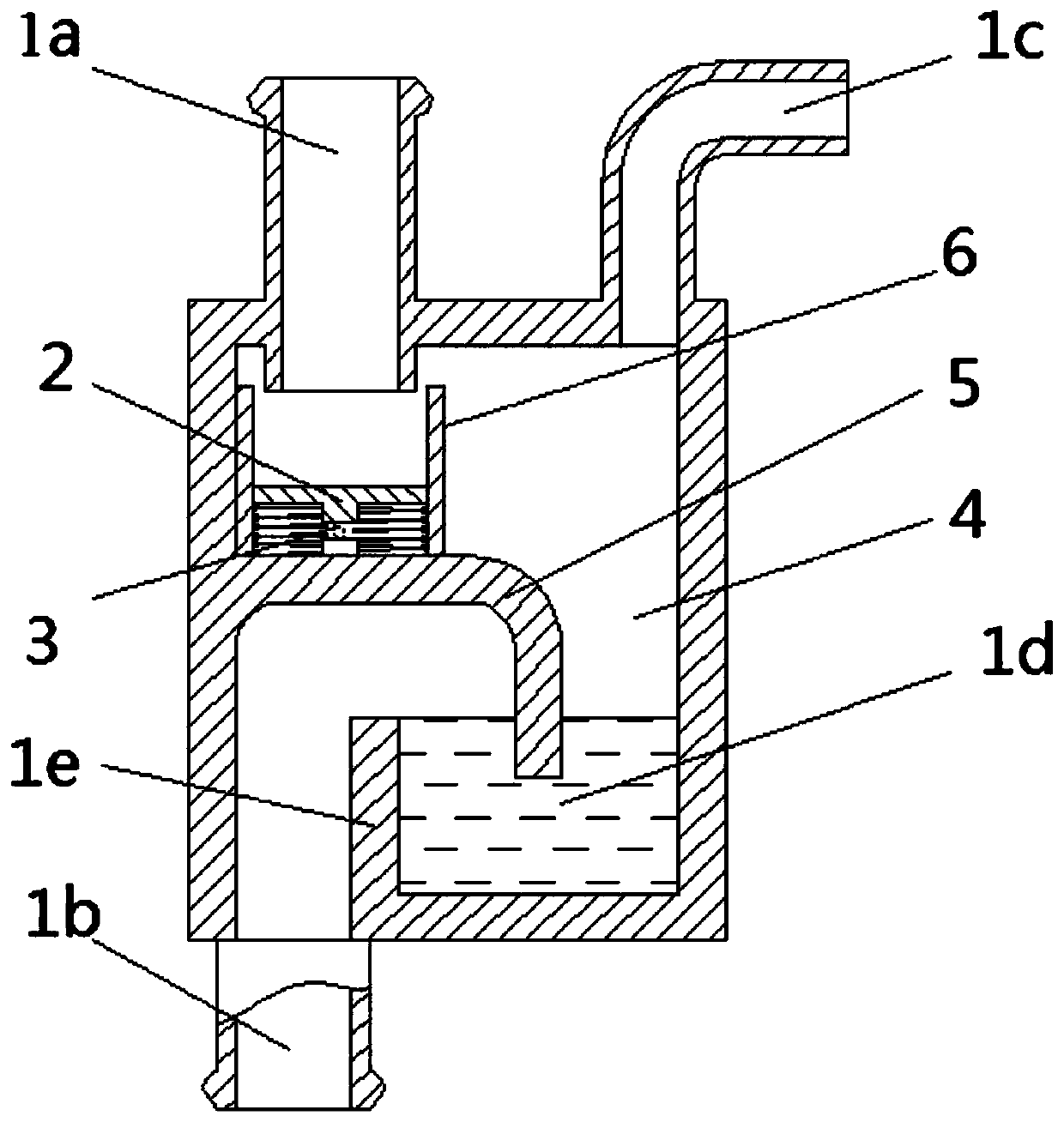
[0021] Figure 1~2 The turbocharger lubricating oil return device shown in includes an oil return cavity 1, and the oil return cavity 1 has an oil inlet 1a connected to the middle of the turbocharger for receiving lubricating oil and for Guide the lubricating oil to the oil outlet 1b and vent 1c in the engine oil pan. The vent 1c is located on the upper part of the oil return cavity and is directly connected to the atmosphere. It can also be connected to the pipeline of the crankcase ventilation system or the turbocharger. The air intake pipeline is connected to connect to the atmosphere indirectly.

[0022] There is an oil storage chamber 4 inside the oil return chamber 1, a U-shaped oil storage tank 1d with an upward opening is arranged at the lower part of the oil storage chamber 4, and an overflow baffle 1e is provided at the edg...


PUM


Abstract

The invention discloses a lubricant oil return device for a turbocharger. The lubricant oil return device comprises an oil return cavity, an oil inlet connected with a middle body of the turbochargerand used for receiving the lubricant and an oil outlet used for leading the lubricant to an oil bottom shell of an engine are formed in the oil return cavity, a ventilating opening and an upward-opening U-shaped oil storing tank are further formed in the oil return cavity, an elastic valve plate assembly for the oil pressure control is arranged at the inner end of the oil inlet, and the oil inletand the ventilating opening are formed in the upper portion of the U-shaped oil storing tank; and the oil outlet is formed in the lower portion of the U-shaped oil storing tank, a partition plate is arranged above the opening of the U-shaped oil storing tank in a hung mode, the partition plate divides the oil return cavity and the U-shaped oil storing tank into an oil-gas partition area and an oil-liquid overflow area, and the lower parts of the oil-gas partition area and the oil-liquid overflow area communicate within the U-shaped oil storing tank. The lubricant oil return device effectivelyprevents the dry friction in the turbocharger without the lubricant during the low oil pressure, the leaked air in the turbocharger is prevented from entering a crankcase through an oil return pipe, the failure rate of the turbocharger is greatly reduced, the maintenance cost is reduced, and the oil consumption is reduced.

Description

technical field [0001] The invention relates to the technical field of automobile engines, in particular to a lubricating oil return device for a turbocharger. Background technique [0002] In recent years, the development of engine technology is changing with each passing day. Whether it is an automobile engine, an aviation piston engine or a marine engine, it is gradually advancing to supercharging. The heat discharged into the atmosphere when the engine is working accounts for 33% of the total heat generated by the engine, and the turbocharger uses the heat in the exhaust gas. The engine is equipped with a turbocharger to reduce emissions, save fuel consumption, and bring greater power performance with a smaller volume. [0003] The turbocharger is actually an air compressor, which is mainly composed of three parts: the turbine, the compressor and the intermediate body. The turbine and the compressor are connected by a drive shaft. The inlet of the turbine is connected t...

Claims


Application Information

Patent Timeline
Patent Type & Authority Patents(China)
IPC IPC(8): F02B39/14
CPCF02B39/14
Inventor 安涛潘亮方仁堂卢顶代勇
Owner DONGFENG COMML VEHICLE CO LTD
Why Eureka
Try Eureka