Valve executor with stable mounting structure

A valve actuator and installation structure technology, applied in the valve shell structure, sliding valve, valve details and other directions, can solve the problems of shortened service life of the actuator, unable to increase the profit of the enterprise, easy damage of the actuator, etc., which is conducive to the exchange of materials. , the effect of reducing economic losses and improving exchange efficiency

Inactive Publication Date: 2019-07-02
兰控阀门执行器江苏有限公司
View PDF5 Cites 2 Cited by
  • Summary
  • Abstract
  • Description
  • Claims
  • Application Information

AI Technical Summary

Problems solved by technology

[0003] The input end and output end of the existing valve actuators are mostly set with two holes in a straight line, resulting in the supporting equipment that needs to be exchanged for material can only be located at the two ends of the straight line of the valve actuator, which may cause the equipment to be mismatched. In fact, the existing linear valve straight-line controller cannot be used, resulting in the need to replace the actuator every time, resulting in a waste of manpower and material resources. It cannot be replaced at the first time, and the existing valve actuator may contain A large amount of water vapor, after the material exchange is completed, the water vapor is left inside the actuator and cannot be discharged, so the actuator is easily damaged, resulting in a shortened service life of the actuator, and the company's profit cannot be increased

Method used


Image

  • Valve executor with stable mounting structure
  • Valve executor with stable mounting structure
  • Valve executor with stable mounting structure

Examples


Embodiment Construction

[0021] The following will clearly and completely describe the technical solutions in the embodiments of the present invention with reference to the accompanying drawings in the embodiments of the present invention. Obviously, the described embodiments are only some, not all, embodiments of the present invention. Based on the embodiments of the present invention, all other embodiments obtained by persons of ordinary skill in the art without making creative efforts belong to the protection scope of the present invention.

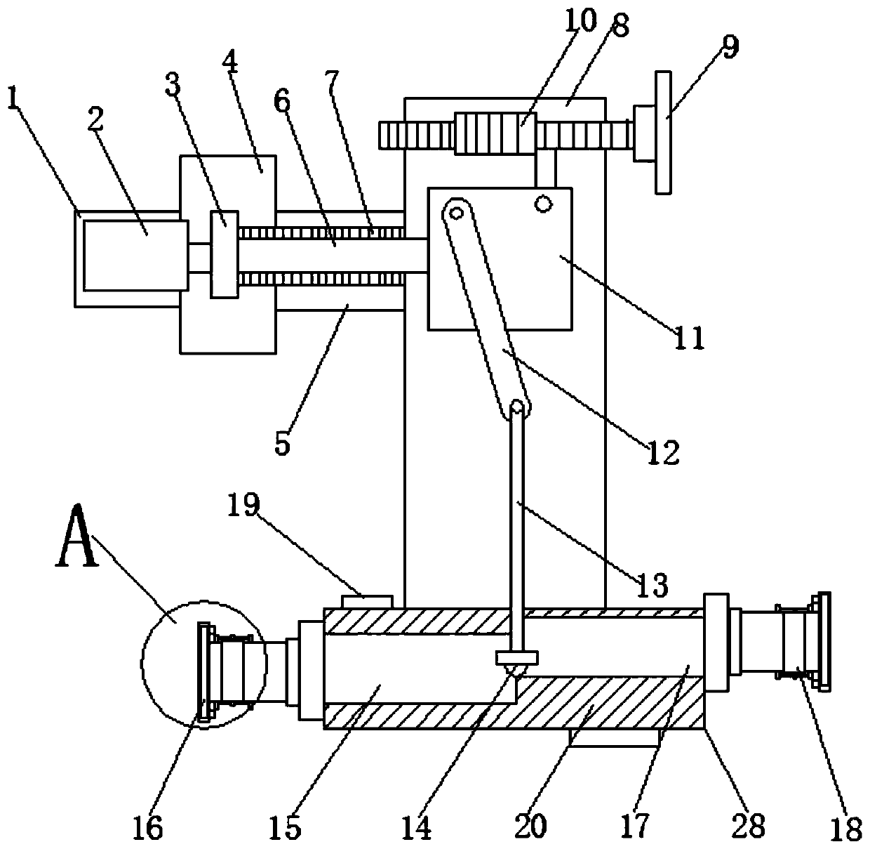
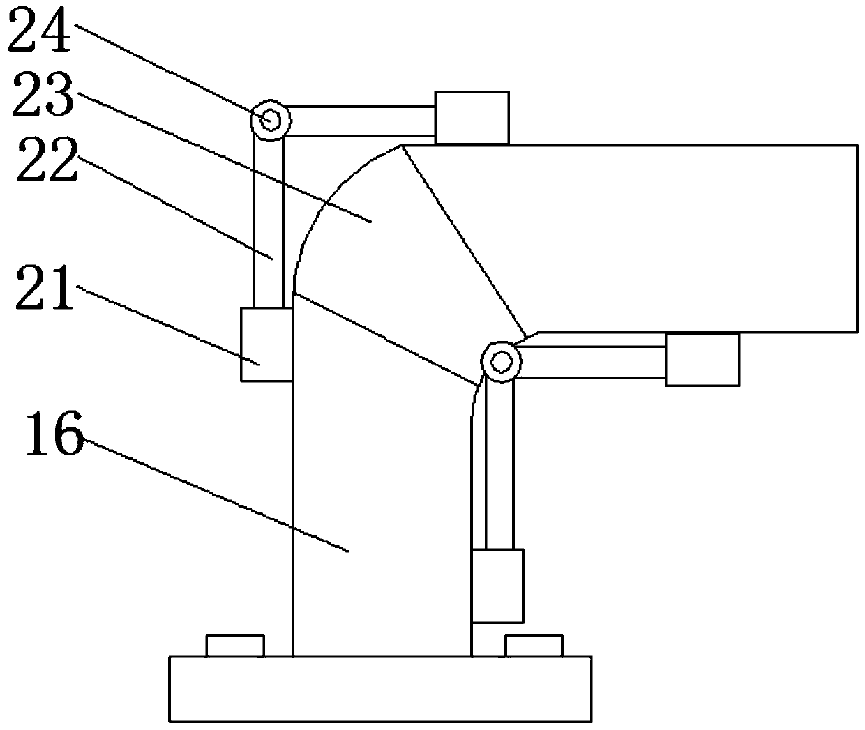
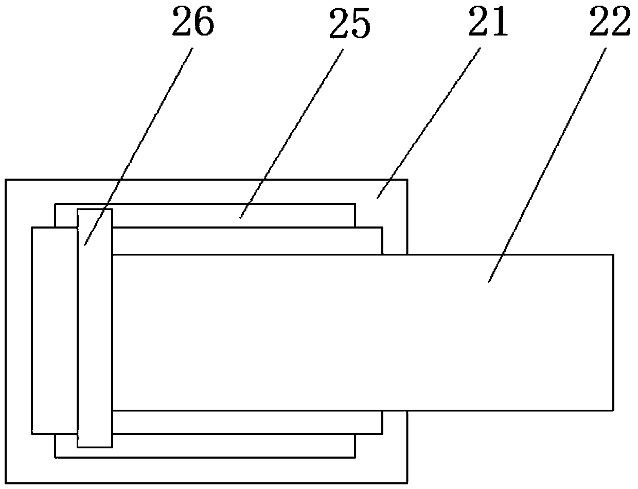
[0022] see Figure 1-5 , a valve actuator with a stable installation structure, including an installation chamber 1, one side of the installation chamber 1 is connected with a connecting pipe 4, and one end of the connecting pipe 4 is provided with a connecting chamber 5, and one side of the connecting chamber 5 is connected with an actuator chamber 8, and the bottom end of the execution chamber 8 is provided with a base 28, the interior of the base 28 is prov...


PUM


Abstract

The invention discloses a valve executor with the stable mounting structure. The valve executor comprises a mounting chamber, a connecting pipe is connected to one side of the mounting chamber, a connecting chamber is arranged on one end of the connecting pipe, an execution chamber is connected to one side of the connecting chamber, a base is arranged on the bottom end of the execution chamber, anair inlet chamber and an air outlet chamber are arranged in the base, one end of the air inlet chamber is connected with an air inlet pipe, and one end of the air outlet chamber is connected with anair outlet pipe. A fixed block, a rotating rod and a hose are arranged, the aim that the air inlet pipe and the air outlet pipe are not fixed structurally is achieved, according to the condition, therotating direction is selected, two sets of devices which are in non-linear connection are conveniently subjected to matter exchange, the valve executor is suitable for matter exchange devices under most conditions, the valve executor has the higher flexibility, the phenomenon that two sets of devices with unmatched angles reject the executor, and a user needs to waste time and labor to seek for the executor meeting the purchasing need is avoided, time is reduced, the exchange efficiency is improved, and economic losses are reduced.

Description

technical field [0001] The invention relates to the field of valve actuators, in particular to a valve actuator with a stable installation structure. Background technique [0002] Pneumatic valve actuator is powered by compressed air. It is a driving device for opening and closing pneumatic ball valves, pneumatic butterfly valves, pneumatic gate valves, pneumatic globe valves, pneumatic diaphragm valves, pneumatic control valves and other pneumatic series angular stroke valves. Or an ideal device for controlling industrial automation pipelines alone. [0003] The input end and output end of the existing valve actuators are mostly set with two holes in a straight line, resulting in the supporting equipment that needs to be exchanged for material can only be located at the two ends of the straight line of the valve actuator, which may cause the equipment to be mismatched. In fact, the existing linear valve straight-line controller cannot be used, resulting in the need to repl...

Claims


Application Information

Patent Timeline
IPC IPC(8): F16K3/02F16K27/04F16K31/12F16K31/44B01D53/28
CPCB01D53/28F16K3/0209F16K3/0254F16K27/04F16K31/12F16K31/44
Inventor 张玉鑫吴鹏贾正晨吴宁宁张玉兵
Owner 兰控阀门执行器江苏有限公司
Why Eureka
Try Eureka