Non-coaxial projection light source system
A light source system, non-coaxial technology, applied in the field of non-coaxial projection light source systems, can solve the problems of large system volume, complex optical path, high cost, and achieve the effect of compact system structure, good dispersion effect, and improved quality.
- Summary
- Abstract
- Description
- Claims
- Application Information
AI Technical Summary
Problems solved by technology
Method used
Image


Examples
Embodiment 1
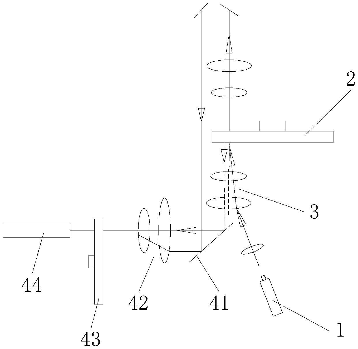
[0029] Such as figure 1 and figure 2 As shown, the non-coaxial projection light source system mainly includes a light source 1, a fluorescent wheel 2, a converging shaping lens group 3 and a light combination assembly;
[0030] The light source 1 adopts a blue laser source, which is collimated and parallel light with good directionality. It is easy to carry out convergence shaping in the optical path, and the control is relatively easy. The convergence shaping lens group 3 is preferably an aspherical lens, which makes more effective use of the difference between radiated fluorescence and excitation light. The light path is separated;
[0031] The light source 1 emits blue laser excitation light, and the excitation light is transmitted to the fluorescent wheel 2 after being converged and shaped by the convergent shaping lens group 3. A number of radiant fluorescent lights of different colors are arranged on the fluorescent wheel 2 along the circumferential direction. The flu...
Embodiment 2
[0036] Such as image 3 and Figure 4 As shown, the difference from Embodiment 1 is that the fluorescent wheel 2 is provided with an excitation light reflection area 23 distributed on the same circumference as the phosphor powder area 21, and the excitation light reflection area 23 replaces the excitation light transmission area 22, and the excitation light reflection area 23 Diffuse reflection of excitation light, such as Figure 4 As shown, the excitation light reflection area 23 may be located on the same side of the fluorescent wheel base as the phosphor powder area 21, and the excitation light reflection area 23 may be formed by coating or other means; Figure 5 As shown, the excitation light reflection area 23 can also be a reflector parallel to the fluorescent wheel arranged on the back side of the fluorescent wheel. The back side of the fluorescent wheel is the side without the phosphor powder area of the fluorescent wheel. It is a Lambertian light source, and the ...
Embodiment 3
[0038] Such as Figure 6 As shown, on the basis of Embodiment 1 and Embodiment 2, a through hole 31 for the excitation light directed to the fluorescent wheel to pass directly through can also be opened on the converging shaping lens group 3, that is, the excitation light incident to the fluorescent wheel 2 The fluorescent wheel 2 is directly irradiated without the converging and shaping effect of the converging and shaping lens group 3, because the blue laser source used in the light source 1 is collimated parallel light with good directionality, which can ensure the excitation efficiency of radiated fluorescence when irradiating the phosphor area. It can better separate the optical path of the excitation light incident to the fluorescent wheel 2 from the optical path of the radiated fluorescence converged by the converging shaping lens group 3. In this scheme, the lenses of the converging shaping lens group 3 can use aspherical lenses or spherical lenses .
PUM
 Abstract
Description
Claims
Application Information
 - R&D
- Intellectual Property
- Life Sciences
- Materials
- Tech Scout
- Unparalleled Data Quality
- Higher Quality Content
- 60% Fewer Hallucinations
Browse by: Latest US Patents, China's latest patents, Technical Efficacy Thesaurus, Application Domain, Technology Topic, Popular Technical Reports.
© 2025 PatSnap. All rights reserved.Legal|Privacy policy|Modern Slavery Act Transparency Statement|Sitemap|About US| Contact US: help@patsnap.com