
Electronic cigarette atomizer

The technology of an electronic cigarette atomizer and atomizer, which is applied in the field of electronic cigarettes, can solve problems such as the deterioration of the quality of smoke taste, the small amount of smoking smoke, and the cracking of electronic cigarette oil, so as to avoid the risk of cracking, increase the amount of smoke, and improve the quality of smoke. The effect of uniformity

Active Publication Date: 2019-07-05
CHINA TOBACCO GUIZHOU IND
View PDF9 Cites 1 Cited by
  • Summary
  • Abstract
  • Description
  • Claims
  • Application Information

AI Technical Summary

Problems solved by technology

[0004] The invention provides an electronic cigarette vaporizer, which solves the uneven heat transfer easily caused by traditional resistance wire heating, and the amount of smoke in the first suction is small; the local temperature is easily too high, which may lead to the cracking of electronic cigarette oil and the taste of smoke. quality deterioration etc.

Method used


Image

  • Electronic cigarette atomizer
  • Electronic cigarette atomizer
  • Electronic cigarette atomizer

Examples


Embodiment 1

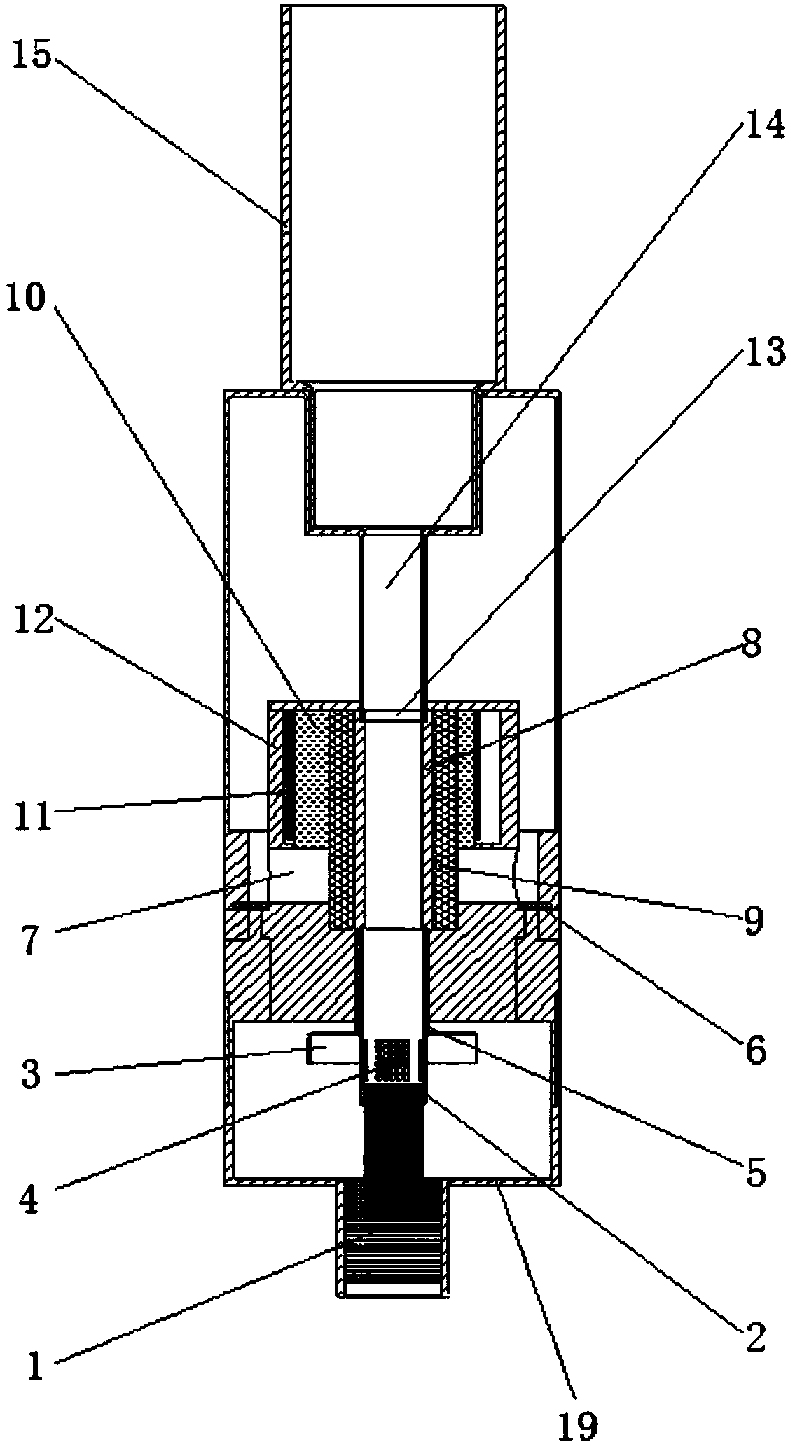
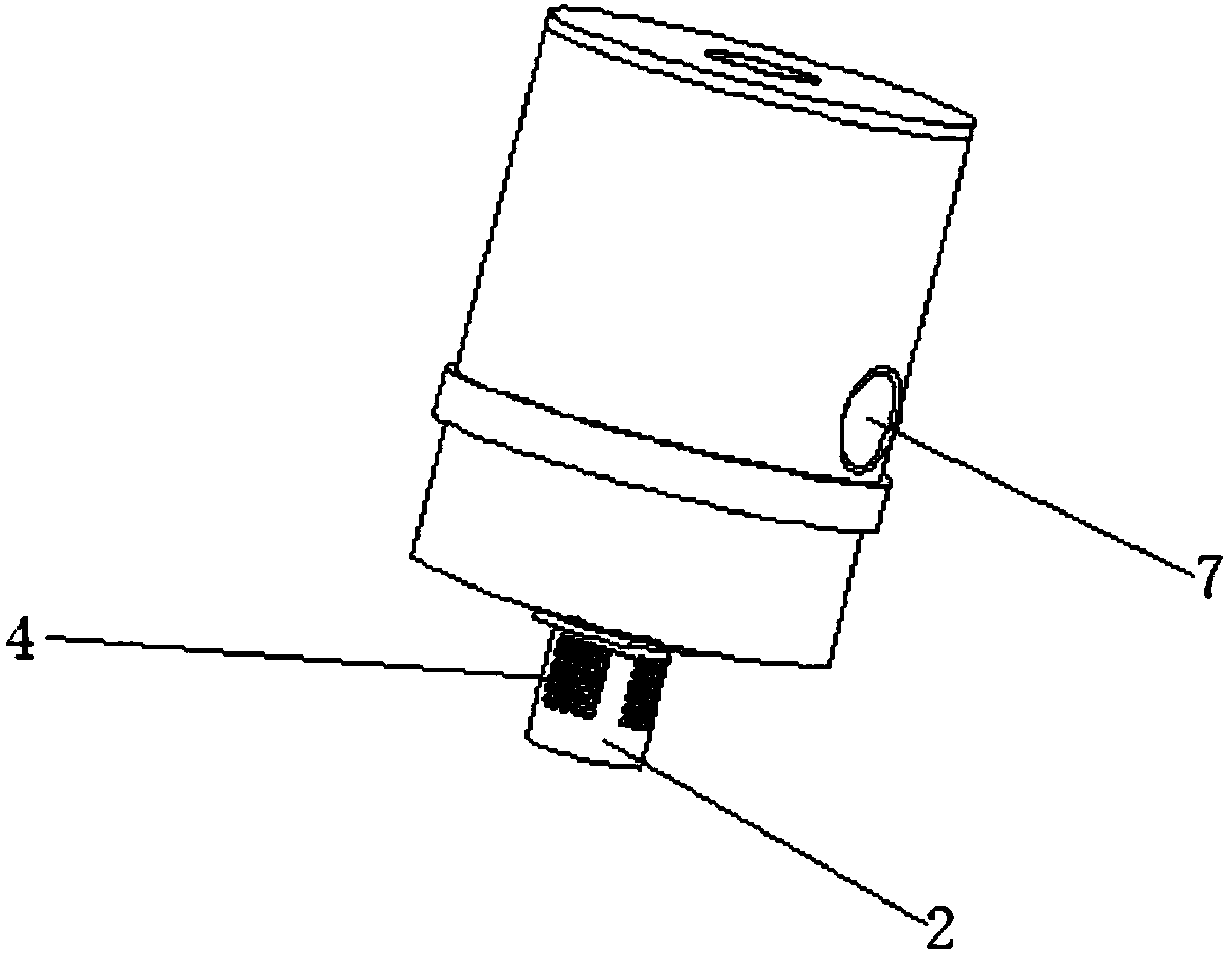
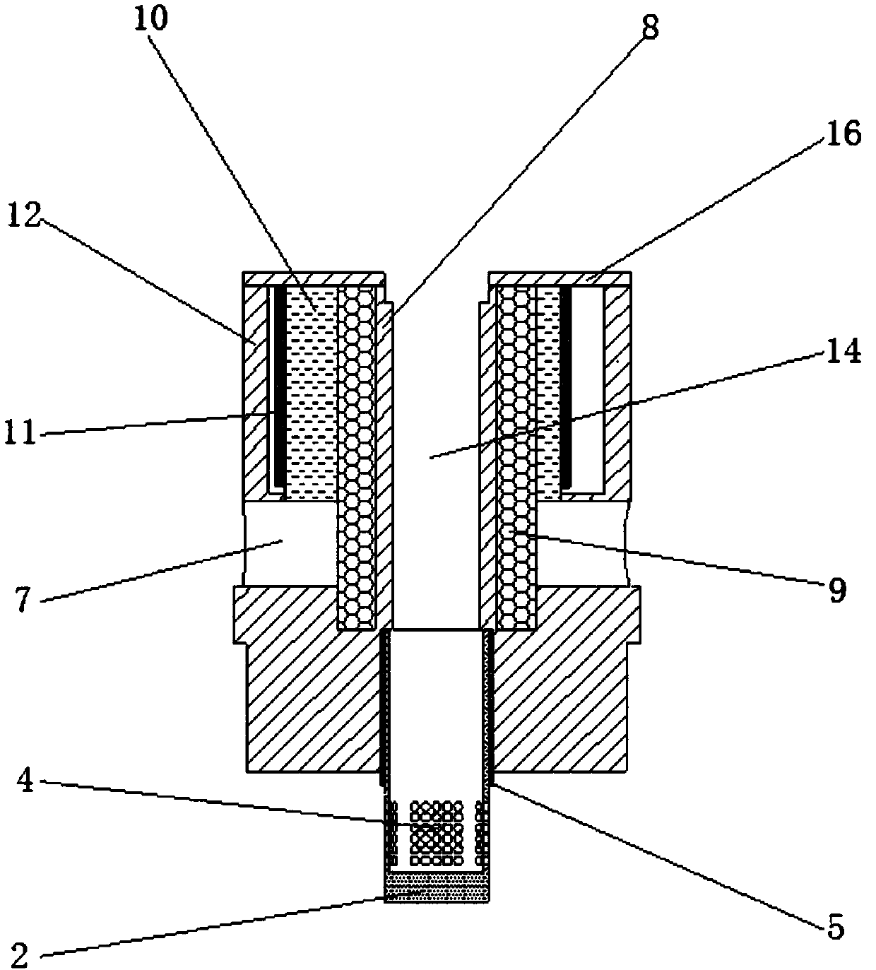
[0030] Such as Figure 1 to Figure 7 As shown, the electronic cigarette atomizer according to Embodiment 1 of the present invention includes an atomizing core, a heating element 11 , an oil carrying element 9 and an oil guiding element 7 .

[0031] The atomizing core has an atomizing cavity and several through holes, and the atomizing cavity communicates with the air flow channel 14 and the suction nozzle 15; the heating element 11 and the oil carrying element 9 are arranged on the In the atomizing core, the oil carrying element 9 communicates with the atomizing chamber; the oil guiding element 7 is arranged in the through hole and communicates with the oil storage chamber 18 and the oil carrying element 9 respectively.

[0032] The atomizing core, the heating element 11 , the oil carrying element 9 and the oil guiding element 7 will be described respectively below.

[0033] (1) atomizing core

[0034] Such as figure 1 As shown, the atomizing core is surrounded by an atomiz...

Embodiment 2

[0066] The difference from the first embodiment is that a heat insulating layer 23 is provided between the heating element 11 and the atomizing core housing 12 to prevent the heat of the heating element 11 from spreading outward.

[0067] Such as Figure 8-10 As shown, the electronic cigarette atomizer according to the second embodiment of the present invention includes an atomizing core. The atomizing core includes a heating element 11 composed of a micro heater, the heating element 11 is connected to the oil carrying element 9, and the oil carrying element 9 communicates with the oil storage chamber 18 through the oil guiding element 7; the oil carrying element 9 communicates with the atomizing chamber, and the atomizing chamber communicates with the airflow channel 14 and the suction nozzle 15 . The oil carrying element 9 is made of organic cotton material, and the oil guiding element 7 is made of organic cotton material. The atomizer is made of materials such as stainles...


PUM


Abstract

The invention provides an electronic cigarette atomizer, and solves the problems that when a traditional resistance wire is used for heating, nonuniform heat transfer can be easily caused; the quantity of smoke inhaled bya person at the first time is small; the local temperature is prone to beingtoo high, so that the electronic tobacco tar pyrolysis can be caused; and the smoke mouthfeel qualityreduction is caused. According to the technical scheme, the electronic cigarette atomizer comprises an atomization core, a heating element, a tar carrying element and tar guide elements, wherein an atomization cavity and a plurality of through holes are formed in the atomization core; the atomization cavity communicates with an air flow passage and a suction nozzle; the heating element and the tarcarrying element are arranged in the atomization core from outside to inside; the tar carrying element communicates with the atomization cavity; and the targuide elements are arranged in the throughholes, and communicate with atar storing cavity and the tar carrying element.

Description

technical field [0001] The invention relates to the technical field of electronic cigarettes, in particular to an electronic cigarette vaporizer. Background technique [0002] E-cigarettes are used to replace traditional cigarettes. The main way to achieve this is to atomize non-toxic and side-effect e-liquid into smoke through an atomizer, so that smokers can get a cigarette-like feeling by atomizing the smoke. [0003] At present, the most commonly used e-liquid atomization method for e-cigarette vaporizers is resistance wire heating. The e-liquid is in direct contact with the resistance wire, resulting in uneven heat transfer and a small amount of smoke in the first puff; the local temperature is likely to be too high. It leads to the cracking of e-cigarette oil to produce harmful substances, causing sensory quality and safety problems of e-cigarette products. In addition, the resistance wire is generally a metal alloy material, and heavy metal elements may migrate into ...

Claims


Application Information

Patent Timeline
Patent Type & Authority Applications(China)
IPC IPC(8): A24F47/00
Inventor 胡世龙刘剑惠建权王维维黄新民阮艺斌胡硕万强
Owner CHINA TOBACCO GUIZHOU IND
Learn More