
Non-woven fabric laminating machine capable of automatically replacing discharging roller shaft

A technology of automatic replacement and cloth laminating machine, which is applied in the direction of thin material processing, coiling, transportation and packaging, etc. It can solve the problems of intermittent work of the laminating machine, hidden safety hazards, and low production efficiency, so as to improve work efficiency. Efficiency, simple structure, and the effect of meeting the needs of use

Inactive Publication Date: 2019-07-05
安徽省卓创信息科技服务有限公司
View PDF6 Cites 0 Cited by
  • Summary
  • Abstract
  • Description
  • Claims
  • Application Information

AI Technical Summary

Problems solved by technology

[0004] After the lamination of the non-woven fabric laminating machine is completed, the rolled non-woven fabric needs to be removed from the discharge frame, and then a new roller is placed on the frame to continue the discharge. At present, manual handling is usually used , or the way of forklift handling to discharge the material, the work efficiency is low, the discharge is inconvenient, and there are potential safety hazards. The new roller shaft usually needs to be placed on the frame manually after the laminating machine is suspended, which will make the laminating machine Work intermittently, low productivity

Method used

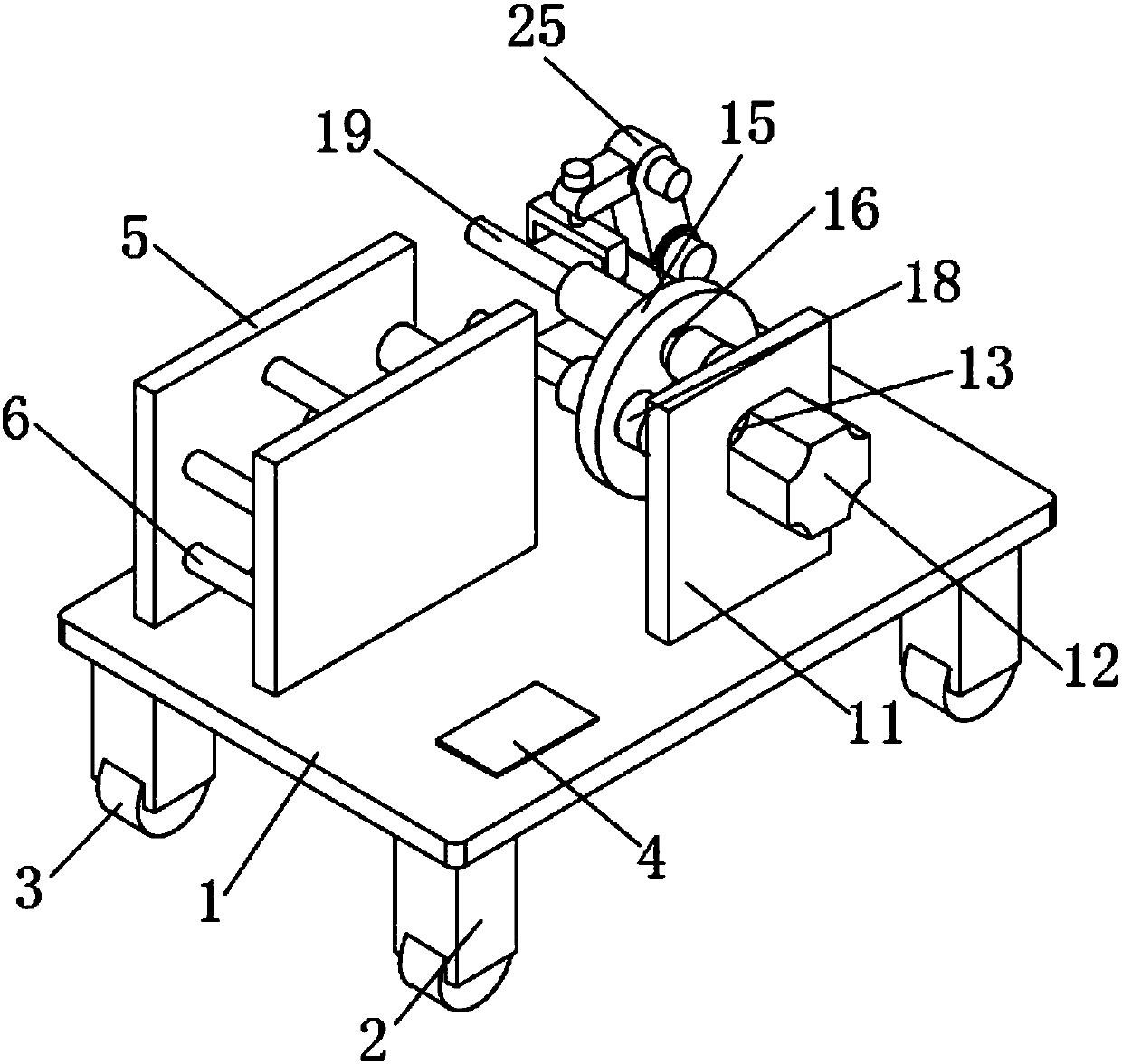
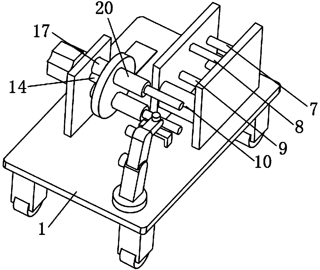
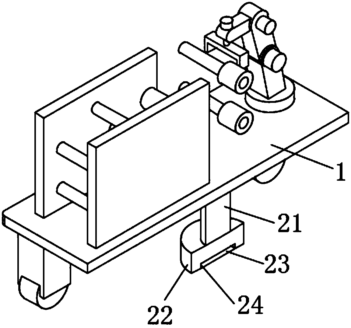

Image

  • Non-woven fabric laminating machine capable of automatically replacing discharging roller shaft
  • Non-woven fabric laminating machine capable of automatically replacing discharging roller shaft
  • Non-woven fabric laminating machine capable of automatically replacing discharging roller shaft

Examples


Embodiment Construction

[0022] The following will clearly and completely describe the technical solutions in the embodiments of the present invention with reference to the accompanying drawings in the embodiments of the present invention. Obviously, the described embodiments are only some, not all, embodiments of the present invention. Based on the embodiments of the present invention, all other embodiments obtained by persons of ordinary skill in the art without making creative efforts belong to the protection scope of the present invention.

[0023] see Figure 1-3 , the present invention provides a technical solution: a non-woven fabric laminating machine with automatic replacement of the discharge roller, including a workbench 1, the edge of the lower end surface of the workbench 1 is provided with feet 2, and the number of feet 2 is not less than four The legs 2 are evenly distributed on the edge of the lower end surface of the worktable 1, and the lower ends of the legs 2 are provided with roll...


PUM


Abstract

The invention discloses a non-woven fabric laminating machine capable of automatically replacing a discharging roller shaft. The non-woven fabric laminating machine comprises a workbench, wherein supporting legs are arranged on the edge of the lower end surface of the workbench, rollers are arranged at the lower ends of the supporting legs, an electric telescopic rod is arranged at the lower end of the workbench, two first vertical plates which are opposite to each other are arranged at the left side of the left side of the upper end face of the workbench, a first material shaft and a second material shaft are arranged on the left side between the two first vertical plates, a first tension adjusting shaft and a second tension adjusting shaft are arranged in the middle of the two first vertical plates, and the height of the first tension adjusting shaft is larger than that of the second material shaft. The non-woven fabric laminating machine is simple in structure and convenient to use;the automatic replacement of a new material roller can be realized on the premise that uninterrupted mechanical work is ensured, the time required for replacing the material roller is reduced, and the working efficiency is improved; and meanwhile, the fixing of the device can be realized on the premise of ensuring the movement of the device, and the special use requirements of a user can be met.

Description

technical field [0001] The invention relates to the technical field of non-woven fabric processing equipment, in particular to a non-woven fabric laminating machine with automatic replacement of a discharge roller. Background technique [0002] A non-woven fabric is a non-woven fabric composed of oriented or random fibers. The difference between non-woven fabrics and woven fabrics is that it is reinforced by mechanical, thermal bonding, chemical and other methods. Since there are no warp and weft threads, cutting and sewing are more convenient than woven fabrics, and they are generally easy to process. Non-woven fabrics are soft, breathable, light and non-toxic. It has the advantages of toxicity, antibacterial and environmental protection. It is a new generation of environmentally friendly materials. [0003] The non-woven fabric laminating machine can add a layer of polymer film on the surface of the non-woven fabric, so as to conveniently endow the surface of the non-wove...

Claims


Application Information

Patent Timeline
IPC IPC(8): B65H19/30
CPCB65H19/30B65H19/305B65H2701/174
Inventor 奉正中
Owner 安徽省卓创信息科技服务有限公司
Learn More