
RF MEMS switch based on superlubricity structure

A technology of switch structure and sliding part, applied in the field of RFMEMS switch based on super-slip structure and its realization, can solve the problems of increasing the mechanical strength of the device, reducing the response speed of the device, failure, etc., so as to achieve no friction loss, stable device performance, Long service life effect

Active Publication Date: 2019-07-05
BEIJING TSITEC CO LTD
View PDF4 Cites 1 Cited by
  • Summary
  • Abstract
  • Description
  • Claims
  • Application Information

AI Technical Summary

Problems solved by technology

No matter what kind of drive is used for these existing RF MEMS switches, their structural methods have common defects: one is that the movable parts of the existing devices are all suspended, and in the case of long-term use, they are easily deformed by the influence of gravity The second is that the restoring force of the existing devices all relies on the mechanical strength of the MEMS device itself for elastic recovery (using the principle similar to a spring), and in the case of long-term use, it is prone to fatigue and deformation
It can be seen that the suspended cantilever beam and the bridge are pulled by gravity under the two states of switching and eventually lead to deformation; at the same time, the mechanical recovery of the cantilever beam and the bridge will also cause deformation after fatigue. The distance between the moving part and the fixed part changes, which will affect the design response speed, loss, Q value, etc., and will eventually cause the performance of the RF MEMS switch to decline or even fail.
[0005] For this reason, this field provides some solutions, such as increasing the size of the cantilever beam and the bridge, so that the mechanical strength of the device is increased to resist deformation; or the distance between the movable part and the fixed part of the switch device is enlarged, To reserve a margin for deformation, but doing so will sacrifice the performance of the device. The former prevents the device from being further miniaturized, and the latter reduces the response speed of the device.

Method used


Image

  • RF MEMS switch based on superlubricity structure
  • RF MEMS switch based on superlubricity structure
  • RF MEMS switch based on superlubricity structure

Examples


Embodiment Construction

[0036] Embodiment 1 of the present invention will be further described below in conjunction with accompanying drawing:

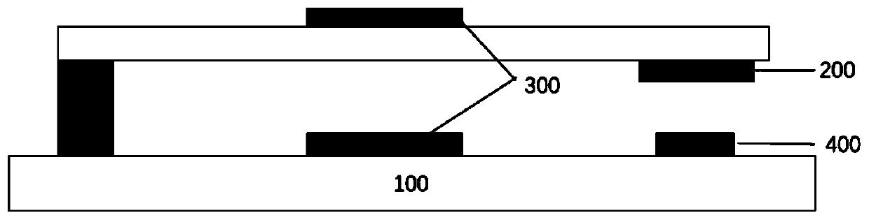
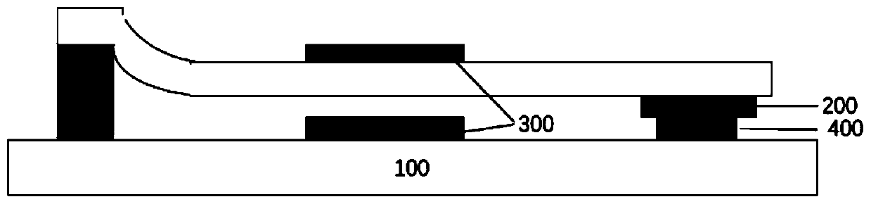
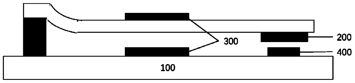
[0037] See attached Figure 3(a) , 3(b) , the present invention provides a kind of RF MEMS switch, and this RF MEMS switch comprises substrate 1, the fixed part that horizontally arranges on described substrate 1, movable part and drive part; Wherein described fixed part comprises fixed part contact electrode 9; wherein the driving part comprises a driving electrode 10; wherein the movable part comprises a self-supporting part 2 and a slidable part 3 composed of self-recoverable graphite islands; a metal cover 4 is formed on the slidable part 3, The metal cover 4 is an optional structure and can also be omitted; a driven electrode 6 and a movable part contact electrode 8 are formed on the metal cover 4; 8 is formed with a second insulating layer 7, in this embodiment 1, the driven electrode 6 is located above the movable part contact electrode 8, but in fa...


PUM


Abstract

The invention provides an RF MEMS switch and an implementation method thereof. The RF MEMS switch includes a substrate, and a group including a fixed portion, a movable portion and a driving portion which are horizontally arranged above the substrate, wherein the movable portion includes a self-supporting portion composed of a self-recoverable graphite island and a slidable portion; the driving portion can drive the slidable portion to move horizontally on the self-supporting portion, so that a contact electrode used in cooperation with the fixed portion and the movable portion can realizes switching. The RF MEMS switch has a long service life and stable device performance because the slidable portion is always supported by the self-supporting portion and utilizes Van der Waals force as arestoring force to avoid deformation caused by gravity and mechanical fatigue.

Description

technical field [0001] The invention belongs to the technical field of radio frequency micro-electromechanical system switches (RF MEMS Switch), and in particular relates to an RF MEMS switch based on a superslip structure and a realization method thereof. Background technique [0002] With the development of radar and wireless communication technology, small size, low power consumption, high performance and multi-functional radio frequency equipment has become the development trend in the radio field, and radio frequency devices are developing in the direction of miniaturization and integration, and MEMS switches emerge as the times require , RF MEMS switches have gradually replaced traditional GaAs FET switches and become the development direction of RF switches (RF Switch). Compared with traditional switches, RFMEMS switches have the advantages of lower insertion loss, higher isolation, better linearity, lower power consumption, smaller volume, etc., and can be easily int...

Claims


Application Information

Patent Timeline
IPC IPC(8): H01H1/00H01H59/00
CPCH01H1/0036H01H59/0009
Inventor 杨德智张清卿
Owner BEIJING TSITEC CO LTD
Features
  • Generate Ideas
  • Intellectual Property
  • Life Sciences
  • Materials
  • Tech Scout
  • Unparalleled Data Quality
  • Higher Quality Content
  • 60% Fewer Hallucinations
Learn More