Novel waste gas treatment apparatus

A waste gas treatment device, a new technology, applied in the direction of gas treatment, use of liquid separation agent, membrane technology, etc., can solve the problems of surrounding working environment pollution, high power consumption or fuel consumption, poor air cleaning effect, etc., to reduce manual operations , Small footprint and compact structure

Inactive Publication Date: 2019-07-09
李金奇
View PDF10 Cites 2 Cited by
  • Summary
  • Abstract
  • Description
  • Claims
  • Application Information

AI Technical Summary

Problems solved by technology

[0003] In some paints, pharmaceuticals, chemicals, etc., where a large amount of waste gas is generated, because the waste gas contains a large amount of harmful bacteria, viruses and organic gases, and these substances emit a foul smell, it is an important factor causing air pollution, especially garbage. This is especially true for waste gas from treatment stations. Existing waste gas treatment systems generally add chemicals to sterilize or burn the waste gas. The waste gas combustion treatment tends to produce highly toxic dioxin gas that cannot be degraded, which easily causes secondary pollution and burns Exhaust gas needs to consume a lot of electricity or fuel, and the investment in combustion equipment is high. Adding medicine or fuel also requires a large amount of capital investment during use, and the operating cost is high. If the exhaust gas is not treated in time, it will pollute the surrounding working environment , thus causing greater harm to the human body, but the current exhaust gas treatment device has poor exhaust gas treatment efficiency and poor air cleaning effect

Method used


Image

  • Novel waste gas treatment apparatus
  • Novel waste gas treatment apparatus

Examples


Embodiment Construction

[0016] The present invention will be further explained below in conjunction with the accompanying drawings, but the protection scope of the present invention will not be limited.

[0017] In the description of the present invention, it should be noted that the orientation or positional relationship indicated by the terms "upper", "lower", "left", "right", "inner" and "outer" are based on the Orientation or positional relationship is only for the convenience of describing the present invention and simplifying the description, and does not indicate or imply that the referred device or element must have a specific orientation, be constructed and operated in a specific orientation, and thus should not be construed as a limitation of the present invention.

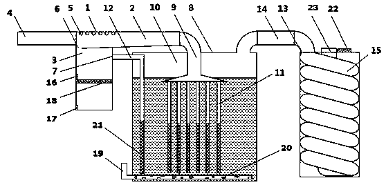
[0018] see figure 1 , the present invention provides a technical solution, a new waste gas treatment device, including a settling device 1, the settling device 1 includes a settling pipeline 2 and a collection box 3, and the se...


PUM


Abstract

The invention discloses novel waste gas treatment apparatus. A sedimentation device comprises a sedimentation pipeline and a collection box, wherein the sedimentation pipeline is arranged on the collection box, nozzles are arranged at the top of the sedimentation pipeline, a sedimentation port communicating with the collecting tank is formed at the bottom of the sedimentation pipeline, and a wastegas outlet is formed in one side of the collecting tank; a treatment device comprises a water tank provided with an air inlet main pipe, wherein the air inlet main pipe is connected with a pluralityof air inlet branch pipes which are arrayed in an array mode, the water tank is provided with an air inlet pipe communicating with the waste gas outlet; and a discharging device comprises an ozone generator and an exhaust pipe. The apparatus is ingenious in design, compact in structure and small in occupied area; the sedimentation device can be used to timely and thoroughly carry out sedimentationtreatment on dust in waste gas, and treatment efficiency is high; the treatment device can be used for storing all reactants, so that gas emitted to the air can meet relevant requirements of the environment protection department; and the discharging device can effectively remove residual harmful substances and peculiar smells in the waste gas. The novel waste gas treatment apparatus can be used for multistage purification treatment, is high in purification efficiency, is environmentally friendly and free of pollution, is convenient to maintain, has low cost and is convenient for popularization and application.

Description

technical field [0001] The invention belongs to the field of waste gas treatment, and in particular relates to a novel waste gas treatment device. Background technique [0002] Exhaust gas treatment is also called exhaust gas purification. Waste gas treatment refers to the pretreatment of waste gas generated in industrial sites and factory workshops before being discharged to the outside, so as to meet the national standards for external discharge of waste gas. General waste gas treatment includes organic waste gas treatment, dust waste gas treatment, acid-base waste gas treatment, odor waste gas treatment and air sterilization, disinfection and purification. Industrial waste gas treatment equipment is widely used in chemical plants, pharmaceutical plants, rubber plants, galvanizing workshops, petrochemical industries and other places where dust, odor, and smoke are generated. [0003] In some paints, pharmaceuticals, chemicals, etc., where a large amount of waste gas is g...

Claims


Application Information

Patent Timeline
Patent Type & Authority Applications(China)
IPC IPC(8): B01D47/06B01D53/76
CPCB01D47/06B01D53/04B01D53/76B01D2251/104B01D2253/102B01D2257/90
Inventor 李金奇
Owner 李金奇
Why Eureka
Try Eureka