Engineering driller capable of efficiently discharging slag

An engineering drilling rig and high-efficiency technology, applied in the directions of rotary drilling rigs, drill bits, drill pipes, etc., can solve the problems of reducing the drilling efficiency of the drilling rig, increasing the labor intensity of workers, energy consumption, etc., to improve the slag removal efficiency, simple structure, and energy saving. Effect

Pending Publication Date: 2019-07-09
天明(南京)智能装备科技有限公司
View PDF1 Cites 10 Cited by
  • Summary
  • Abstract
  • Description
  • Claims
  • Application Information

AI Technical Summary

Problems solved by technology

For example, the publication number is a kind of rotary drilling rig CN202209151U. During the use of this rotary drilling rig, when the drilling slag in the drill bit needs to be discharged, the drill rod and the drill bit need to be taken out simultaneously. Frequently taking out the drill rod and the drill bit will greatly Reduce the drilling efficiency of the drilling rig, and consume more energy, while increasing the labor intensity of the workers

Method used


Image

  • Engineering driller capable of efficiently discharging slag
  • Engineering driller capable of efficiently discharging slag
  • Engineering driller capable of efficiently discharging slag

Examples


Embodiment 1

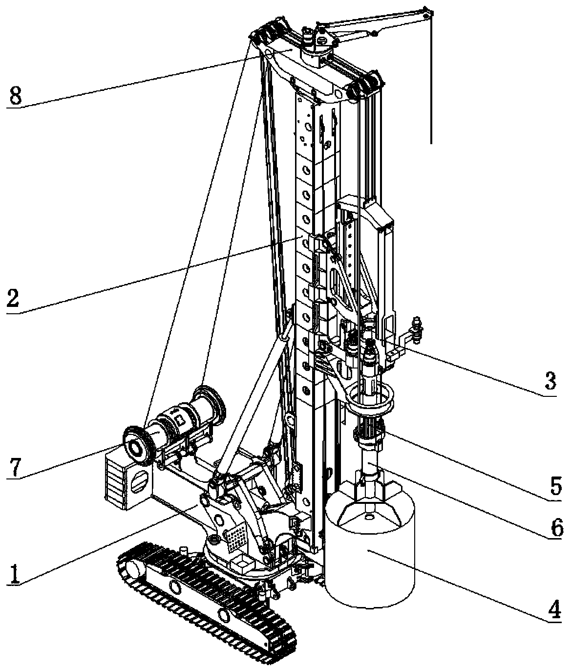
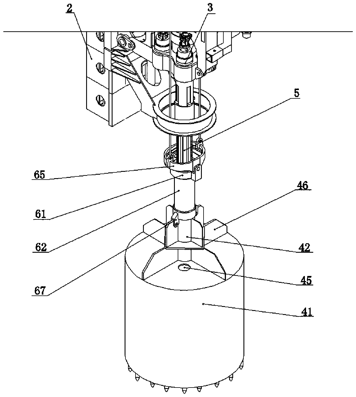
[0026] Embodiment 1, a kind of engineering drilling rig of efficient slagging, refer to figure 1 , including a drilling rig body 1, a drilling tower 2 is installed on the front end of the drilling rig body 1, a power head 3 is installed on the drilling tower 2, and a drilling tool assembly is installed on the power head 3, refer to figure 2 , the drilling tool assembly includes a rotary drilling bit 4, a drill pipe assembly and a slip ring assembly 6;

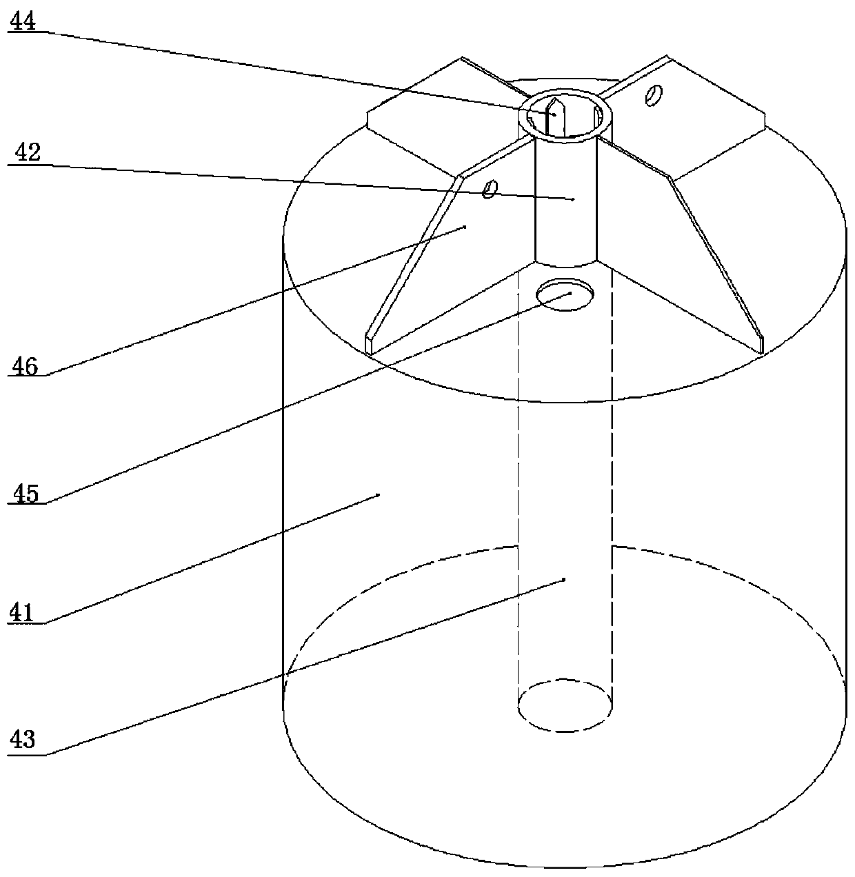
[0027] refer to image 3 and Figure 4 , the rotary drilling bit 4 includes a cylinder 41, the top of the cylinder 41 is provided with a loam cake, and the center of the loam cake is fixedly provided with a torsion transmission sleeve 42, and the torsion transmission sleeve 42 is fixedly provided with a torsion transmission inner spline 44, and the torsion transmission The axis of the sleeve 42 is collinear with the axis of the cylinder 41, and a sealing tube 43 connected to the lower end of the torque transmission sleeve 42...

Embodiment 2

[0031] Embodiment 2. In the high-efficiency slag discharge engineering drilling rig described in Embodiment 1: the bottom end of the sealing pipe 43 and the bottom end of the cylinder body 41 are at the same level.

Embodiment 3

[0032] Embodiment 3, a high-efficiency slagging engineering drilling rig described in Embodiment 1 or 2: the bottom of the cylinder 41 is fixedly equipped with drill teeth.


PUM


Abstract

An engineering driller capable of efficiently discharging slag relates to the technical field of drilling equipment, and is mainly used for solving the problem of low deslagging efficiency of drillingslag. The engineering driller capable of efficiently discharging slag comprises a driller body, a drill tower is mounted at the front end of the driller body, a power head is mounted on the drill tower, a drilling tool assembly is mounted on the power head, and the drilling tool assembly comprises a rotary excavating drill bit, a drill rod assembly and a slip ring assembly; the rotary excavatingdrill bit comprises a barrel, an upper cover is arranged at the top of the barrel, a torque transmission sleeve is fixedly arranged in the center of the upper cover, and a torque transmission internalspline is fixedly arranged in the torque transmission sleeve; the drill rod assembly comprises a torque transmission drill rod and a plurality of upper drill rods, the slip ring assembly comprises astatic ring and a movable ring, a winch used for lifting the rotary excavating drill bit is fixedly installed on the driller body, and a pulley block is installed at the top of the drill tower. The rotary excavating drill bit can be pulled out of the drill rod to discharge drilling slag, the slag discharging efficiency of drilling is greatly improved, energy is saved, and the engineering driller has the advantages of being simple in structure, convenient to use, high in slag discharging efficiency, capable of saving energy and the like.

Description

technical field [0001] The invention relates to the technical field of drilling equipment, in particular to an engineering drilling rig for efficient slag discharge. Background technique [0002] With the needs of production development, drilling rigs are widely used in various engineering construction fields. Due to the differences in drilling materials and operating environments, people have developed many different types of drilling rigs for various conditions of use, most of which need to drive the drill bit through the drill pipe to complete the drilling work. For example, the publication number is a kind of rotary drilling rig CN202209151U. During the use of this rotary drilling rig, when the drilling slag in the drill bit needs to be discharged, the drill rod and the drill bit need to be taken out simultaneously. Frequently taking out the drill rod and the drill bit will greatly Reduce the drilling efficiency of the drilling rig, and consume more energy, while increa...

Claims


Application Information

Patent Timeline
Patent Type & Authority Applications(China)
IPC IPC(8): E21B3/02E21B19/02E21B10/62E21B27/00E21B17/00E21B17/046
CPCE21B3/02E21B10/62E21B17/00E21B17/046E21B19/02E21B27/00
Inventor 卢明立刘祥军刘攀军邱国东苏云辉
Owner 天明(南京)智能装备科技有限公司
Why Eureka
Try Eureka