Three-band laser antireflection film and preparation method thereof

A three-band, anti-reflection coating technology, applied in optics, optical components, ion implantation plating, etc., can solve problems such as poor adhesion and peeling, and achieve easy control, strong adhesion of the film layer, and excellent optical performance Effect

Pending Publication Date: 2019-07-09
NANJING WAVELENGTH OPTO ELECTRONICS SCI & TECH CO LTD
View PDF10 Cites 4 Cited by
  • Summary
  • Abstract
  • Description
  • Claims
  • Application Information

AI Technical Summary

Problems solved by technology

[0005] In order to solve the problems of delamination, peeling and poor adhesion of the film layer, so that the obtained film layer has both good spectral performance and good mechanical stability and stability, the present invention provides a 10.6μm&1570nm&650nm three-band laser anti-reflection Membrane and its preparation method

Method used


Image

  • Three-band laser antireflection film and preparation method thereof
  • Three-band laser antireflection film and preparation method thereof
  • Three-band laser antireflection film and preparation method thereof

Examples


Embodiment 1

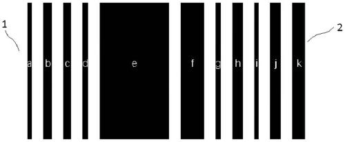
[0036] Such as figure 1 As shown, a three-band laser anti-reflection coating includes a base layer, including a base layer, and the base layer is sequentially deposited with the first YF 3 layer, the first ZnSe layer, the second YF 3 layer, the second ZnSe layer, the third YF 3 layer, the third ZnSe layer, the fourth YF 3 layer, the fourth ZnSe layer, the fifth YF 3 layer, the fifth ZnSe layer and MgF 2 layer; the base layer is a ZnSe base layer.

[0037] The thickness of ZNSE base layer is 2mm, the first YF 3 The thickness of the layer is 204nm, the thickness of the first ZnSe layer is 420nm, the second YF 3 The thickness of the layer is 390nm, the thickness of the second ZnSe layer is 270nm, the third YF 3 The thickness of the layer is 5328nm, the thickness of the third ZnSe layer is 1500nm, the fourth YF 3 The thickness of the layer is 246nm, the thickness of the fourth ZnSe layer is 486nm, the fifth YF 3 The thickness of the layer is 192nm, the thickness of the fi...

Embodiment 2

[0043] A three-band laser anti-reflection coating, including a base layer, including a base layer, the base layer is sequentially deposited with the first YF 3 layer, the first ZnSe layer, the second YF 3 layer, the second ZnSe layer, the third YF 3 layer, the third ZnSe layer, the fourth YF 3 layer, the fourth ZnSe layer, the fifth YF 3 layer, the fifth ZnSe layer and MgF 2 layer; the base layer is a ZnSe base layer.

[0044] The thickness of ZNSE base layer is 2mm, the first YF 3 The thickness of the layer is 206nm, the thickness of the first ZnSe layer is 423nm, the second YF 3 The thickness of the layer is 394nm, the thickness of the second ZnSe layer is 265nm, the third YF 3 The thickness of the layer is 5325nm, the thickness of the third ZnSe layer is 1502nm, the fourth YF 3 The thickness of the layer is 249nm, the thickness of the fourth ZnSe layer is 488nm, the fifth YF 3 The thickness of the layer is 195nm, the thickness of the fifth ZnSe layer is 345nm, the M...


PUM

PropertyMeasurementUnit
thicknessaaaaaaaaaa
thicknessaaaaaaaaaa
thicknessaaaaaaaaaa

Abstract

The invention discloses a three-band laser antireflection film and a preparation method thereof. The three-band laser antireflection film comprises a base layer; a composite layer and a MgF2 layer aresequentially deposited on the base layer; the composite layer comprises alternatively deposited YF3 layers and ZnSe layers; the base layer is connected with the YF3 layer; and the MgF2 layer is connected with the ZnSe layer. The three-band laser antireflection film provided by the invention has the single-face reflectivity of not more than 1% at the 650nm band, the single-face reflectivity of notmore than 0.25% at the 1570nm band, the single-face reflectivity of less than 0.25% at the 10.6micron band, meets the operating requirements of the multi-wavelength laser machining equipment opticalsystem, and is good in optical performance, strong in film adhesion and rub resistance, good in water resistance and temperature resistance, good spectrum performance and relatively good mechanical performance and stability, good in preparation repeatability, simple and easy to operate, and easy to control.

Description

technical field [0001] The invention relates to a three-band laser anti-reflection film and a preparation method thereof, belonging to the field of three-band laser anti-reflection films. Background technique [0002] Modern visible / near-infrared spectral analysis technology can make full use of full-spectrum or multi-wavelength spectral data for analysis. It has the characteristics of large amount of information, fast speed, good reproducibility, and convenient measurement. It is widely used in food, agriculture, chemical and fields such as pharmaceuticals. [0003] In modern optical systems, most optical components need to be coated with anti-reflection coatings to reduce surface reflection, especially for special environments and optical systems. In addition to requiring high optical performance of the film, it also needs to be able to resist various harsh environment. [0004] However, existing anti-reflection coatings have problems such as easy delamination, peeling, ...

Claims


Application Information

Patent Timeline
Patent Type & Authority Applications(China)
IPC IPC(8): G02B1/115C23C14/54C23C14/24C23C14/06C23C14/02
CPCG02B1/115C23C14/022C23C14/0623C23C14/0694C23C14/24C23C14/542
Inventor 李全民陈佳佳朱敏吴玉堂王国力
Owner NANJING WAVELENGTH OPTO ELECTRONICS SCI & TECH CO LTD
Why Eureka
Try Eureka