
mems chip structure

A chip structure and ring structure technology, applied in the field of MEMS chips, can solve the problems of complex control of micromirrors and reduced performance, and achieve the effects of small size, reducing the influence of thermal crosstalk, and suppressing thermal crosstalk.

Active Publication Date: 2021-01-05
HUAWEI TECH CO LTD +1
View PDF3 Cites 0 Cited by
  • Summary
  • Abstract
  • Description
  • Claims
  • Application Information

AI Technical Summary

Problems solved by technology

This can lead to extremely complex control of the micromirror and reduced performance

Method used


Image

  • mems chip structure
  • mems chip structure
  • mems chip structure

Examples


Embodiment Construction

[0037] The technical solutions in the embodiments of the present application will be described below with reference to the drawings in the embodiments of the present application.

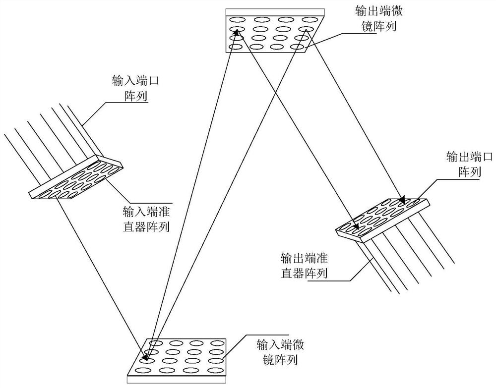
[0038] The application relates to a MEMS chip structure, which is a core device constituting an optical switch in the field of optical switching. figure 1A schematic block diagram of a MEMS optical switch is shown, including an input port array, an input micromirror array, an output micromirror array, and an output port array, wherein the input port array is used to receive optical signals; the input The micromirror array at the end reflects the received optical signal to the micromirror array at the output end; the micromirror array at the output end reflects the optical signal reflected by the micromirror array at the input end to the output port array, thereby sending it out; wherein, the micromirror array at the input end or The micromirrors included in the micromirror array at the output end ca...


PUM


Abstract

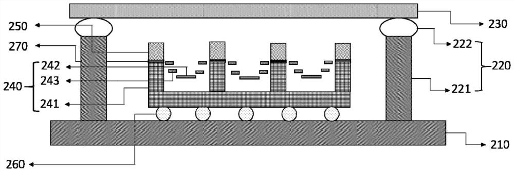
The application discloses a MEMS chip structure, including: a base, a side wall, a dielectric plate, a MEMS micromirror array and a grid array, the side wall is a ring structure, and the base covers an opening on one side of the side wall, The dielectric plate covers the opening on the other side of the side wall, and the side wall, the base and the dielectric plate form a hollow structure; the MEMS micromirror array and the grid array are located in the hollow structure Inside; the MEMS micromirror array is located above the substrate, the MEMS micromirror array includes a plurality of grooves and a plurality of MEMS micromirrors, wherein the plurality of MEMS micromirrors and the plurality of grooves are one One-to-one correspondence, the plurality of MEMS micromirrors are located in the corresponding grooves or above the grooves; the grid array is located above the MEMS micromirror array, and the lower surface of the grid array is in contact with the grid array. The upper surface of the side wall of at least part of the grooves in the plurality of grooves is connected.

Description

technical field [0001] The present application relates to the field of MEMS chips, in particular to a structure of an electrothermal MEMS chip. Background technique [0002] Due to the advantages of large scanning angle, low driving voltage, low manufacturing cost, and simple control, electrothermal microelectromechanical system (MEMS) micromirrors have attracted much attention in the fields of optical imaging, medical detection, microdisplay, and optical communication. Especially in the field of optical communication, the electrothermal MEMS micromirror array chip with large rotation angle is suitable for assembling large-scale optical cross-connect (optical cross-connect, OXC) modules. [0003] However, after the electrothermal MEMS micromirror is integrated in the array, there is a problem of thermal crosstalk; when one or more micromirrors adjacent to the working micromirror start to work, the heat generated will change the ambient temperature distribution around the wor...

Claims


Application Information

Patent Timeline
Patent Type & Authority Patents(China)
IPC IPC(8): G02B26/08B81B7/02
CPCG02B26/0833B81B7/02B81C1/00317B81B3/0081B81B2203/0163B81B2201/045B81B3/0083B81B2201/042B81B2203/0323G02B26/0866
Inventor 陈奕文黄兆兴姚丹阳汤红蒋臣迪谢会开
Owner HUAWEI TECH CO LTD
Learn More