

Cutting chatter online monitoring method and monitoring system
A technology of monitoring system and numerical control system, applied in the field of mechanical processing, can solve the problems of obtaining process system, aggravation, chatter, etc., and achieve the effect of simple calculation process
- Summary
- Abstract
- Description
- Claims
- Application Information
AI Technical Summary
Problems solved by technology
Method used
Image

Examples
Embodiment 1
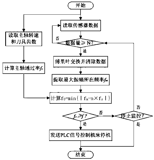
[0030] Such as figure 1 As shown, a cutting chatter online monitoring method is characterized in that: comprising the following steps:
[0031] a. Install the vibration sensor on the spindle of the machine tool, read the sensor data, and at the same time automatically read the spindle speed m in the CNC system, and calculate the spindle passing rate f s =m / 60;
[0032] b. If the amount of sensor data read is greater than or equal to N, then Fourier transform and clear the data; if the amount of data is less than N, return to the read sensor data in step a, where N is the set amount of data;
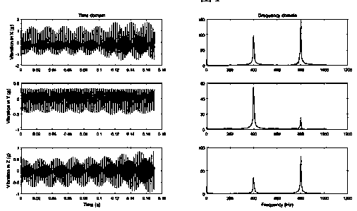
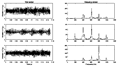
[0033] c. The law between the frequency domain signal and the cutting state is: during stable cutting (no flutter generation), the vibration energy is concentrated in the spindle passing rate f s Integer multiples of frequency; when flutter occurs, the vibration energy deviates from the main axis through the rate f s Integer multiples of frequencies, there will be larger vibrations at ...
Embodiment 2
[0045] Such as figure 1 As shown, a cutting chatter online monitoring method, including the following steps:
[0046]a. Install the vibration sensor on the spindle of the machine tool, read the sensor data, and at the same time automatically read the spindle speed m in the CNC system, and calculate the spindle passing rate f s =m / 60;
[0047] b. If the amount of sensor data read is greater than or equal to N, then Fourier transform and clear the data; if the amount of data is less than N, return to the read sensor data in step a, where N is the set amount of data;
[0048] c. The law between the frequency domain signal and the cutting state is: during stable cutting (no flutter generation), the vibration energy is concentrated in the spindle passing rate f s Integer multiples of frequency; when flutter occurs, the vibration energy deviates from the main axis through the rate f s Integer multiples of frequencies, there will be larger vibrations at many other frequencies;
PUM
 Abstract
Description
Claims
Application Information