Control system of LLC converter synchronous rectifier tube

A technology for synchronous rectifiers and control systems, applied in control/regulation systems, conversion of DC power input to DC power output, instruments, etc. The controller detects problems such as deviations to achieve the effect of realizing the length of the conduction time, realizing adaptive control, and realizing driving

Active Publication Date: 2019-07-09
SOUTHEAST UNIV +1
View PDF2 Cites 14 Cited by
  • Summary
  • Abstract
  • Description
  • Claims
  • Application Information

AI Technical Summary

Problems solved by technology

[0003] (1) The method of collecting the synchronous rectification current is the most accurate control method, which can accurately judge the opening and closing of the synchronous rectification tube, but the loss of the sampling resistor used for collecting the current is too large, and it is gradually not used;
[0004] (2) By collecting the drain-source voltage, the turn-off point of the synchronous rectifier will always switch back and forth between the forward conduction and reverse conduction states of the body diode, and the conduction of the body diode will bring additional conduction loss;
[0005] (3) The digital synchronous rectification technology of the microcontroller MCU can realize the adaptive conduction of the synchronous rectifier tube, but at high frequencies, due to the influence of parasitic parameters in the system, the difficulty of acquisition will increase, resulting in false opening and the occurrence of false shutdown
These parasitic parameters will cause the turn-on and turn-off of the synchronous rectifier to generate high-frequency oscillation signals, which will cause deviations in the detection of the sampling circuit or the microcontroller, thereby causing wrong control signals to be generated for the drive of the synchronous rectifier, affecting The working state of the converter reduces the working efficiency of the converter

Method used


Image

  • Control system of LLC converter synchronous rectifier tube
  • Control system of LLC converter synchronous rectifier tube
  • Control system of LLC converter synchronous rectifier tube

Examples


Embodiment Construction

[0031] The technical solution of the present invention will be described in detail below in conjunction with the accompanying drawings.

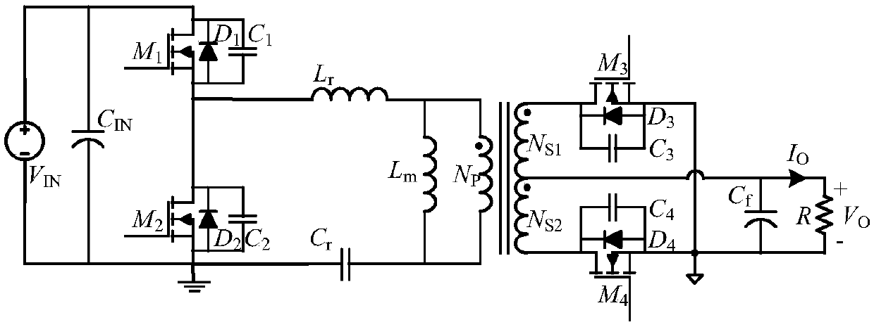
[0032] like figure 1 , the circuit components of the existing synchronous rectification LLC resonant converter include the power tube M on the primary side of the transformer 1 , M 2 , the resonant capacitor Cr, the resonant inductance Lr and the exciting inductance Lm, the synchronous rectifier tube M on the secondary side of the transformer 3 , M 4 , output capacitor Cf and load R, etc. Among them, D 1 、D 2 Respectively power tube M 1 , M 2 The parasitic diode, C 1 、C 2 M respectively 1 , M 2 The parasitic capacitance, D 3 、D 4 Respectively synchronous rectifier tube M 3 , M 4 The parasitic diode, C 3 、C 4 Respectively synchronous rectifier tube M 3 , M 4 of parasitic capacitance.

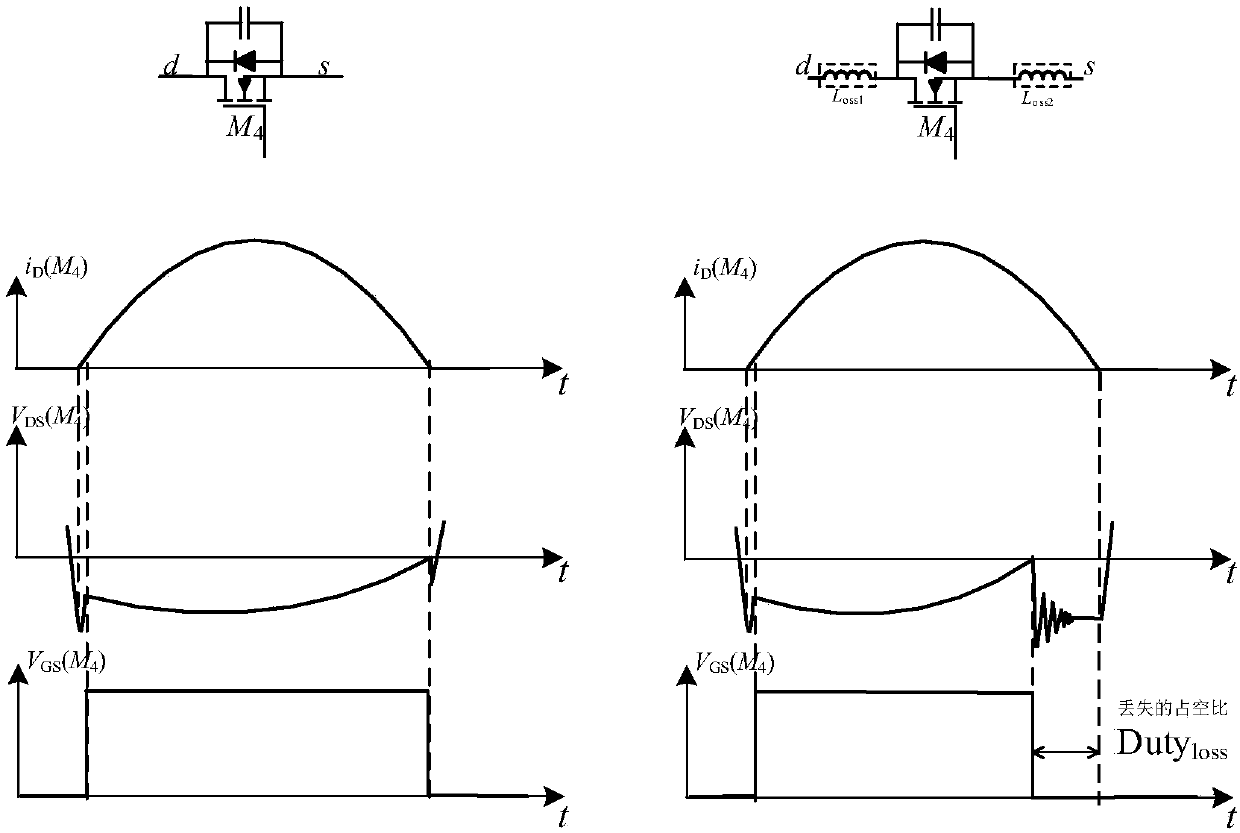
[0033] like figure 2 , when the LLC resonant converter operates at low frequency and high frequency, the effect of parasitic inductance o...


PUM


Abstract

Disclosed is a control system of an LLC converter synchronous rectifier tube. The control system comprises a voltage sampling circuit, a high-pass filter circuit, a PI compensation and effective valuedetection circuit and a control circuit which takes a microcontroller MCU as a core. A principle of circuit waveform oscillation caused by unavoidable parasitic inductance and parasitic capacitance in the circuit is utilized, and when an LLC converter works at high frequency, a drain source voltage VDS (SR) of the synchronous rectifying tube sends a change signal of the drain source voltage in aswitch-off period into the high-pass filter circuit and the PI compensation and effective value detection circuit through the sampling circuit to obtain an effective value amplifying signal of a drainsource voltage oscillation signal caused by parasitic parameters; and the control circuit which takes the microcontroller MCU as the core is adopted to compare the relation between a current value and a collected value in the last time, so that the conduction time of the synchronous rectification tube in the next cycle is changed, the synchronous rectifier tube can be switched off at the optimalswitch-off point, and the optimal efficiency operation of the synchronous rectifier tube can be realized.

Description

technical field [0001] The invention relates to a control method of a synchronous rectifier tube of an LLC converter (resonant converter), in particular to a control system of a synchronous rectifier tube of an LLC resonant converter. Background technique [0002] With the continuous development of power technology, the LLC resonant converter has gradually become a recognized power topology. It has the inherent ZVS turn-on of the primary power tube and the ZCS turn-off advantage of the synchronous rectifier, which enables it to achieve higher efficiency than other traditional topologies. However, when the LLC resonant converter works at low voltage and high current output, due to the large on-resistance of the rectifier diode, its loss is greatly increased, thereby reducing the working efficiency. The proposal of synchronous rectification technology, by using the conduction of the power tube instead of the diode, because the conduction resistance of the power tube is smalle...

Claims


Application Information

Patent Timeline
Patent Type & Authority Applications(China)
IPC IPC(8): H02M3/335
CPCH02M3/33592H02M3/01H02M3/33571Y02B70/10H02M3/33584H02M3/33515H02M1/0016H02M1/0058
Inventor 钱钦松许胜有林峰王浩苏巍刘琦时龙兴
Owner SOUTHEAST UNIV
Why Eureka
Try Eureka