
Self-adaptive adjusting circuit and self-adaptive adjusting method for evaluation phase duration of asynchronous SAR analog-to-digital converter

An analog-to-digital converter and self-adaptive adjustment technology, applied in the communication field, achieves the effect of low cost and increased chip area

Active Publication Date: 2019-07-09
成都盛芯微科技有限公司
View PDF8 Cites 8 Cited by
  • Summary
  • Abstract
  • Description
  • Claims
  • Application Information

AI Technical Summary

Problems solved by technology

Usually the delay unit is implemented using the delay of the logic unit, and there will be a large change under different voltage / temperature / process angles

Method used


Image

  • Self-adaptive adjusting circuit and self-adaptive adjusting method for evaluation phase duration of asynchronous SAR analog-to-digital converter
  • Self-adaptive adjusting circuit and self-adaptive adjusting method for evaluation phase duration of asynchronous SAR analog-to-digital converter
  • Self-adaptive adjusting circuit and self-adaptive adjusting method for evaluation phase duration of asynchronous SAR analog-to-digital converter

Examples


Embodiment 1

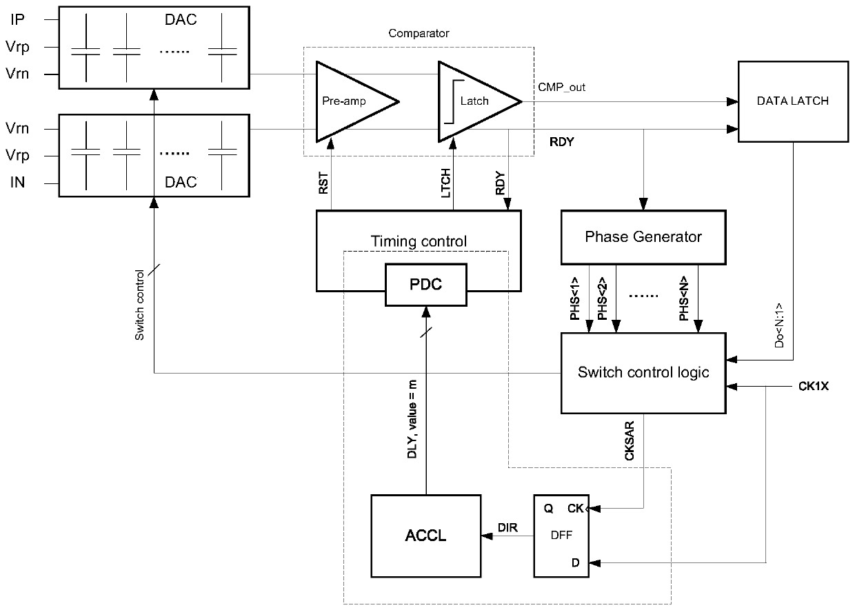
[0042] like image 3 As shown, on the basis of the structure of the usual asynchronous SARADC, this embodiment adds: a programmable delay unit, a clock edge comparator, and a comparison phase duration adaptive control logic, specifically:

[0043] 1) Programmable delay unit (PDC, programmable delay cell), such as Figure 4 As shown, it is used to provide the settling time of the DAC and Pre-amp. For the convenience of description, the input control and delay amount of the delay unit are simplified. The input is m, and the corresponding delay DLY(m) is generated. The larger m is, the greater the delay is, that is, the greater DLY(m) is. m has a maximum value m_max and a minimum value m_min, which is determined by its control word length. There are many ways to implement the PDC.

[0044] 2) Clock edge comparator (CEC, clock edge comparator), such as Figure 5 As shown, it uses the comparison completed flag bit CKSAR as input A, the externally provided sampling cloc...

Embodiment 2

[0059] This embodiment adopts PHS (k=1,2,...,N) as the input A of CEC, that is, use PHS To replace CKSAR, through the loop control of CEC+ACCL, PHS will eventually The rising edge of CK1X is roughly aligned with the rising edge of CK1X, and PHS has a total of N phases, resulting in a final SARADC comparison evaluation phase duration of about (N / k)*T / 2. In the design of high-speed SARADC, according to application requirements and design difficulty, a certain sampling time is sometimes borrowed to make up for the lack of comparison evaluation time.

[0060] like Figure 12 As shown, in this embodiment, a data selector (MUX) is added between the phase generator (PhaseGenerator) and the D-type flip-flop (DFF), and PHS_SEL is used to select the corresponding PHS output to the DFF, that is, PHS_SEL selects a certain channel of PHS To replace the CKSAR signal, extend the time of the comparison evaluation phase of the SARADC. The purpose of doing this is usually to improve th...


PUM


Abstract

The invention discloses a self-adaptive adjusting circuit and a self-adaptive adjusting method for evaluation phase duration of an asynchronous SAR analog-to-digital converter. According to the invention, a clock edge comparator, a comparison phase time length adaptive control logic unit and a programmable control delay unit form a control loop, so that the evaluation phase time length of the SARanalog-to-digital converter is controlled. According to the invention, the time length of the evaluation phase of the asynchronous SAR analog-to-digital converter can be controlled to be close to a half of a clock period under all voltages, temperatures or process angles, adjustment is self-adaptive, the problem that the sampling time is insufficient due to the fact that the comparison time is toolong under a process angle SS is solved, and the problem that the establishment time of the digital-to-analog converter and the pre-amplifier is insufficient under a process angle FF is solved. In addition, the cost is extremely low, and the chip area is hardly increased.

Description

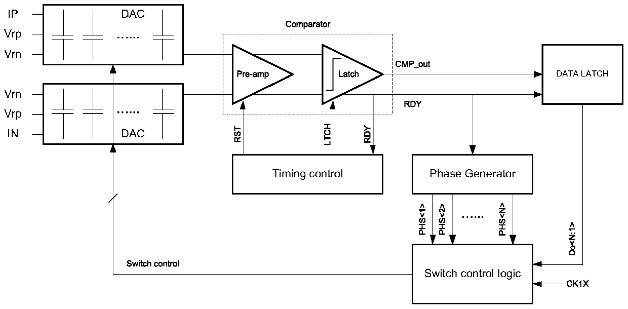
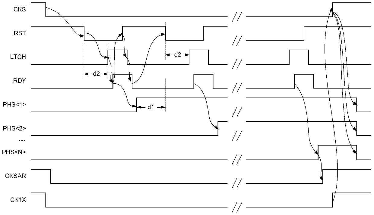
technical field [0001] The invention relates to the technical field of communications, and in particular, to an adaptive adjustment circuit and method for evaluating the phase length of an asynchronous SAR analog-to-digital converter. Background technique [0002] Asynchronous successive approximation analog-to-digital converter (SAR ADC, Successive Approximation RegisterAnalog-to-Digital Converter), such as figure 1 As shown, only the sampling clock (CK1X, period is T) needs to be provided externally, and the asynchronous SAR ADC will use the internal asynchronous logic for timing control, which is easy to achieve high speed and low power consumption, and greatly simplifies the external clock requirements. also better, as figure 2 Shown is the timing for a typical asynchronous SARADC. Generally, when the falling edge of the sampling clock comes, the asynchronous SARADC ends the sampling phase and enters the comparison phase of successive comparison. A Mbit asynchronous ...

Claims


Application Information

Patent Timeline
IPC IPC(8): H03M1/46
CPCH03M1/468
Inventor 张歆杨毅陈怡
Owner 成都盛芯微科技有限公司
Learn More