Eureka AIR delivers breakthrough ideas for toughest innovation challenges, trusted by R&D personnel around the world.

Hump rolling process monitoring system and method

A process monitoring and hump slipping technology, applied in the measurement of force, measurement device, and force measurement by measuring the change of optical properties of materials when they are stressed, which can solve the problem of low spatial resolution, inability to continuous, real-time monitoring, and inability to Realize the monitoring of the hump slipping process and other issues to achieve the effect of ensuring safety and improving marshalling efficiency

Active Publication Date: 2019-07-12
WUHAN UNIV OF TECH
View PDF7 Cites 10 Cited by
  • Summary
  • Abstract
  • Description
  • Claims
  • Application Information

AI Technical Summary

Problems solved by technology

The system can monitor the track occupancy by using the fiber grating sensor to count the train axle, but the fiber grating sensor belongs to the point detection, which can only detect a limited number of points, and the spatial resolution is very low. Continuous and real-time monitoring of the running status of the train on the entire track cannot be carried out, so the monitoring of the hump rolling process cannot be realized
[0007] To sum up, there is currently no good method to realize the real-time monitoring of the train sliding process in the marshalling yard, especially the real-time monitoring and early warning of the train running status, location information and abnormal conditions

Method used


Image

  • Hump rolling process monitoring system and method
  • Hump rolling process monitoring system and method
  • Hump rolling process monitoring system and method

Examples


Embodiment Construction

[0038] In order to make the object, technical solution and advantages of the present invention clearer, the present invention will be further described in detail below in conjunction with the accompanying drawings and embodiments. It should be understood that the specific embodiments described here are only used to explain the present invention, not to limit the present invention.

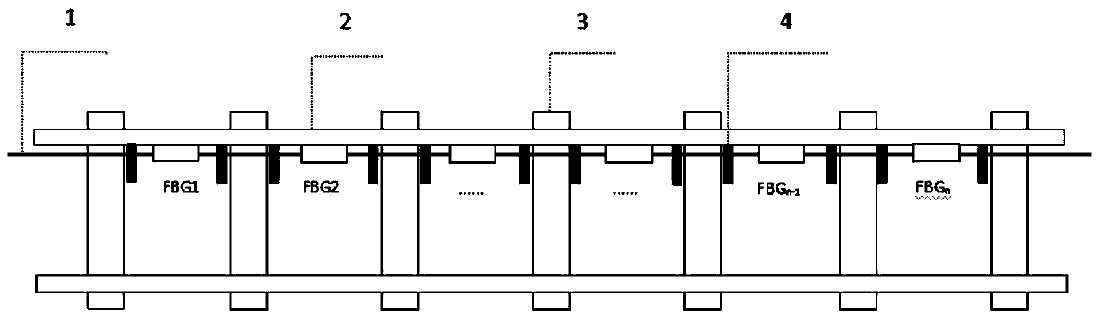
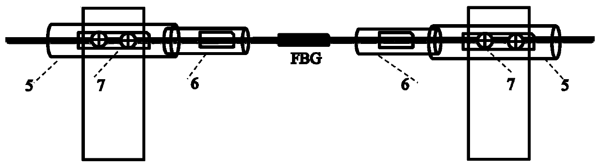
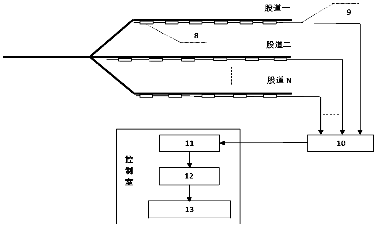
[0039] The hump slipping process monitoring system of the embodiment of the present invention, such as figure 1 , figure 2 and image 3 shown, including:

[0040] A plurality of optical grating array sensing cables 1, each grating array sensing optical cable 1 is provided with a number of fiber grating sensing units at equal intervals, each grating array sensing optical cable 1 corresponds to a sliding track 2 to be tested, and the optical fiber grating sensing The unit is fixedly installed between two adjacent sleepers 3; several fiber grating sensors are sequentially installed between two adj...


PUM

PropertyMeasurementUnit
reflectanceaaaaaaaaaa

Abstract

The invention discloses a hump rolling process monitoring system. The hump rolling process monitoring system comprises multiple grating array sensing optical cables, an optical fiber splice closure, an optical fiber grating demodulator, a computer and a train rolling information display, wherein optical fiber grating sensors are arranged on each grating array sensing optical cable in an equally spaced manner; each grating array sensing optical cable is laid on one rolling track to be detected; the optical fiber grating sensors are mounted between two adjacent sleepers; the optical fiber spliceclosure gathers the grating array sensing optical cables on multiple detected station tracks through transmission cables; the optical fiber grating demodulator is connected with the optical fiber splice closure through a multi-core cable to demodulate information collected on site; the computer is connected with the optical fiber grating demodulator to analyze and process demodulated data so as to obtain related information including a position, a speed and a load of a rolling train; and the train rolling information display is connected with the computer to display the related information, obtained from the computer, of the rolling train. According to the hump rolling process monitoring system, the related information, such as the position, the load and the speed, in the rolling processof the train on a marshaling yard can be monitored in real time.

Description

technical field [0001] The invention relates to optical fiber sensing technology, in particular to a real-time monitoring system and method for a train slipping process in a marshalling yard based on grating array stress and strain sensing technology. Background technique [0002] The hump shunting plant of the railway marshalling station is the main processing plant for reorganizing freight trains according to different purposes. The unloading is divided into two processes: hump unloading and plane unloading. Afterwards, carry out the sliding process until the plane splitting lane; plane sliding refers to the process that the freight train arrives at different shunting lanes through the splitting lane until it stops. During the slipping process, there may be situations such as entering the wrong track, stopping halfway, leaving the track, failing to reach the designated area, etc. In order to ensure the safety of the train slipping, it is very necessary to monitor the slipp...

Claims


Application Information

Patent Timeline
Patent Type & Authority Applications(China)
IPC IPC(8): B61L23/00G01B11/16G01L1/24
CPCB61L23/00G01B11/165G01L1/246
Inventor 甘维兵艾凌云李政颖张翠潘建军唐健冠王立新郭会勇
Owner WUHAN UNIV OF TECH
Why Eureka
Eureka Blog
Learn More