
Liquid ammonia conversion equipment and liquid ammonia conversion method

A technology for converting equipment and liquid ammonia, applied in mechanical equipment, container filling method, container discharge method, etc., can solve the problems of high liquid ammonia storage cost and high investment in spherical tank engineering, and achieve low bearing capacity, low engineering investment, The effect of low storage costs

Pending Publication Date: 2019-07-12
CIMC ENRIC ENGINEERING TECHNOLOGY CO LTD
View PDF0 Cites 2 Cited by
  • Summary
  • Abstract
  • Description
  • Claims
  • Application Information

AI Technical Summary

Problems solved by technology

[0003] The object of the present invention is to provide a liquid ammonia conversion equipment and a liquid ammonia conversion method to solve the problem that liquid ammonia under normal temperature and pressure is stored in spherical tanks, and the engineering investment of spherical tanks is relatively high, resulting in high storage costs for liquid ammonia. The problem

Method used


Image

  • Liquid ammonia conversion equipment and liquid ammonia conversion method
  • Liquid ammonia conversion equipment and liquid ammonia conversion method
  • Liquid ammonia conversion equipment and liquid ammonia conversion method

Examples


Embodiment Construction

[0026] In order to make the object, technical solution and advantages of the present invention more clear, the present invention will be further described in detail below in conjunction with the accompanying drawings and embodiments. It should be understood that the specific embodiments described here are only used to explain the present invention, not to limit the present invention.

[0027] In describing the present invention, it should be understood that the terms "center", "longitudinal", "transverse", "length", "width", "thickness", "upper", "lower", "front", " Orientation indicated by rear, left, right, vertical, horizontal, top, bottom, inside, outside, clockwise, counterclockwise, etc. The positional relationship is based on the orientation or positional relationship shown in the drawings, which is only for the convenience of describing the present invention and simplifying the description, rather than indicating or implying that the referred device or element must hav...


PUM


Abstract

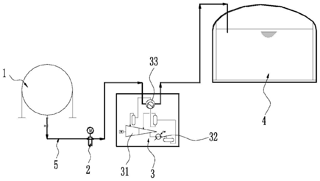
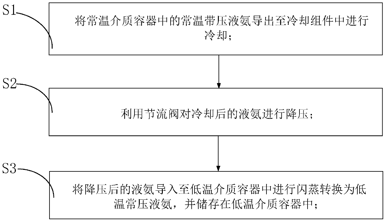
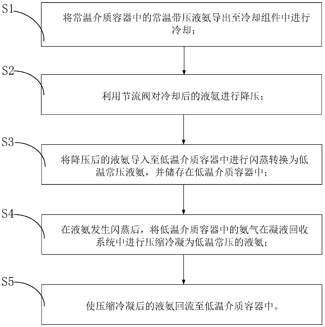
The invention relates to the technical field of chemical production, in particular to liquid ammonia conversion equipment and a liquid ammonia conversion method. The liquid ammonia conversion equipment comprises a constant temperature medium container, a cooling assembly, a throttling valve and a low temperature medium container. The constant temperature medium container is used for storing liquidammonia with a pressure at a constant temperature; the cooling assembly is used for cooling the liquid ammonia in the constant temperature medium container and is connected to the constant temperature medium container through a pipeline; the throttling valve is connected to the cooling assembly through a pipeline for reducing the liquid ammonia output by the cooling assembly to constant pressureand the temperature of the liquid ammonia reduced in pressure is higher than a corresponding boiling point of the liquid ammonia at the constant temperature to flash the liquid ammonia; the low temperature medium container is connected to the throttling valve through a pipeline and providing a flash space for the liquid ammonia at the reduced pressure as well as storing the low-temperature constant pressure liquid ammonia. The low-temperature constant pressure liquid ammonia is stored by the low temperature medium container, the low temperature medium container is relatively low in demand on carrying ability and relatively low in engineering investment, and the storage cost of the liquid ammonia is relatively low.

Description

technical field [0001] The invention relates to the technical field of chemical production, in particular to a liquid ammonia conversion device and a liquid ammonia conversion method. Background technique [0002] Ammonia is the basic raw material for the production of modified ammonium nitrate, ammonium phosphate, nitrophosphate and other ammonia-containing fertilizers and urea. Usually, liquid ammonia is stored in storage tanks under normal temperature and pressure. Due to the high pressure of liquid ammonia under normal temperature and pressure, spherical tanks are usually required for storage. The internal stress of spherical tanks is small and uniform, and the carrying capacity is large. However, the manufacturing, welding and assembly requirements of spherical tanks are relatively strict, and the engineering investment is relatively high, resulting in relatively high storage costs for liquid ammonia. Contents of the invention [0003] The object of the present inven...

Claims


Application Information

Patent Timeline
Patent Type & Authority Applications(China)
IPC IPC(8): F17C7/02F17C5/02F17C13/04F17C13/00
CPCF17C7/02F17C5/02F17C13/04F17C13/00F17C2221/01F17C2223/013F17C2225/013F17C2227/0135F17C2227/0337F17C2227/0358F17C2227/039
Inventor 王洪军梁启周李珏张耀琴
Owner CIMC ENRIC ENGINEERING TECHNOLOGY CO LTD
Learn More