Tunnel section and boundary scanning and detecting device and method

A scanning detection and cross-section technology, which is applied in measurement devices, cross-sectional drawing, and optical devices, etc., can solve the problems of single data application, unsuitable detection technology, low efficiency, etc., and achieve the effect of high detection accuracy.

Pending Publication Date: 2019-07-12
CHINA RAILWAY ENG CONSULTING GRP CO LTD +1
View PDF1 Cites 11 Cited by
  • Summary
  • Abstract
  • Description
  • Claims
  • Application Information

AI Technical Summary

Problems solved by technology

However, there is no attitude correction module and GPS measurement module in this technical solution, so factors that affect the measurement accuracy such as the vibration of the locomotive when running on the track cannot be effectively eliminated, and a 3D point cloud model under a unified coordinate system cannot be established for the full-line scanning data. Not conducive to further mining applications of scanned data
[0007] To sum up, for the census detection of the section and boundary of the operating high-speed railway tunnel, the existing detection technology is either not applicable, or the efficiency is low, or the data application is too single, which cannot be well adapted to the current operation of the high-speed railway on the tunnel section and boundary. Census detection, and the need to establish a 3D point cloud model, therefore, it is necessary to develop new detection technology to meet this demand

Method used


Image

  • Tunnel section and boundary scanning and detecting device and method
  • Tunnel section and boundary scanning and detecting device and method
  • Tunnel section and boundary scanning and detecting device and method

Examples


Embodiment Construction

[0034] The technical solutions in the embodiments of the present invention will be clearly and completely described below in conjunction with the accompanying drawings in the embodiments of the present invention. Obviously, the described embodiments are only a part of the embodiments of the present invention, not all the embodiments. Based on the embodiments of the present invention, all other embodiments obtained by those of ordinary skill in the art without creative work shall fall within the protection scope of the present invention.

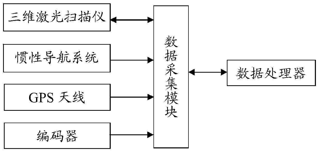
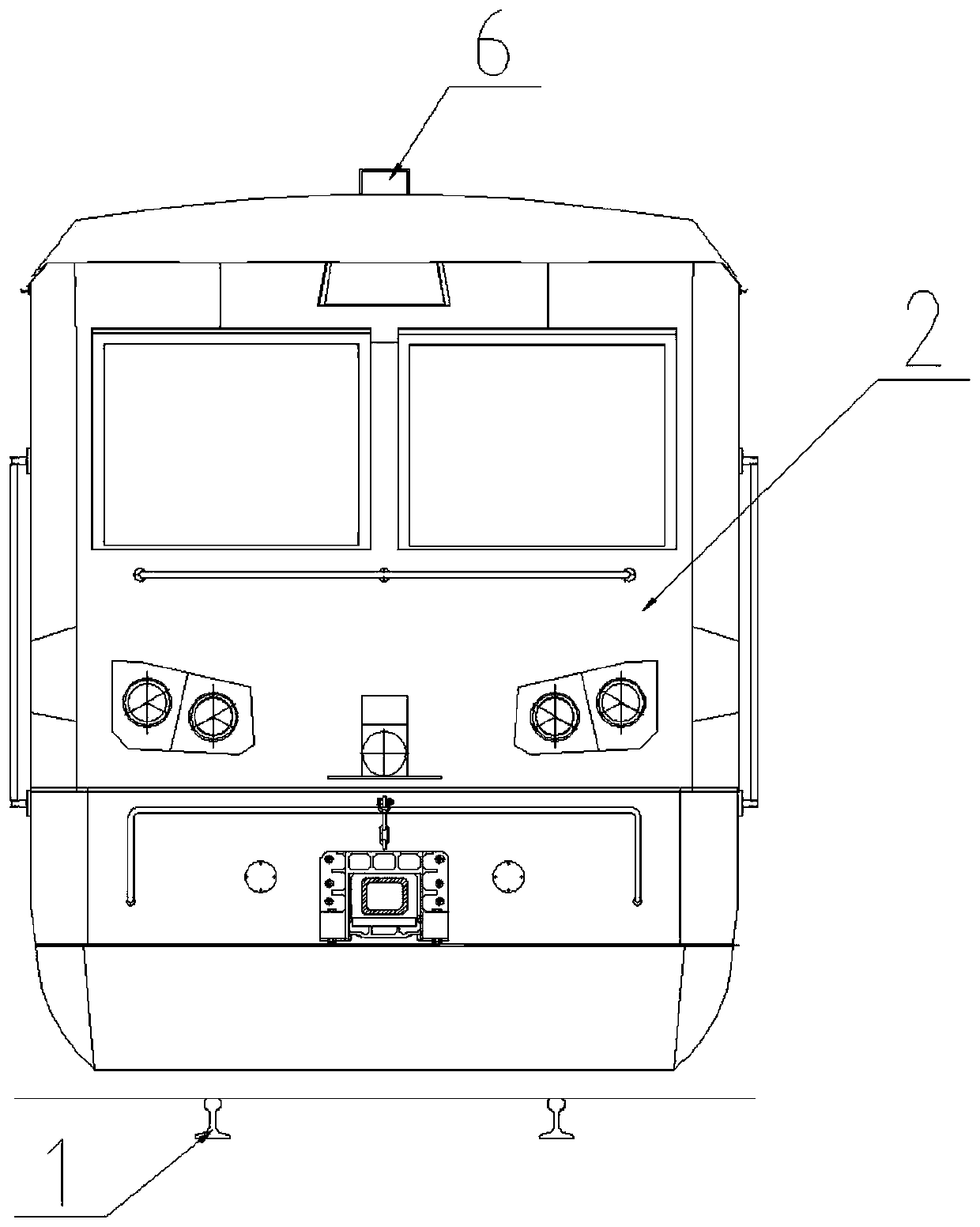
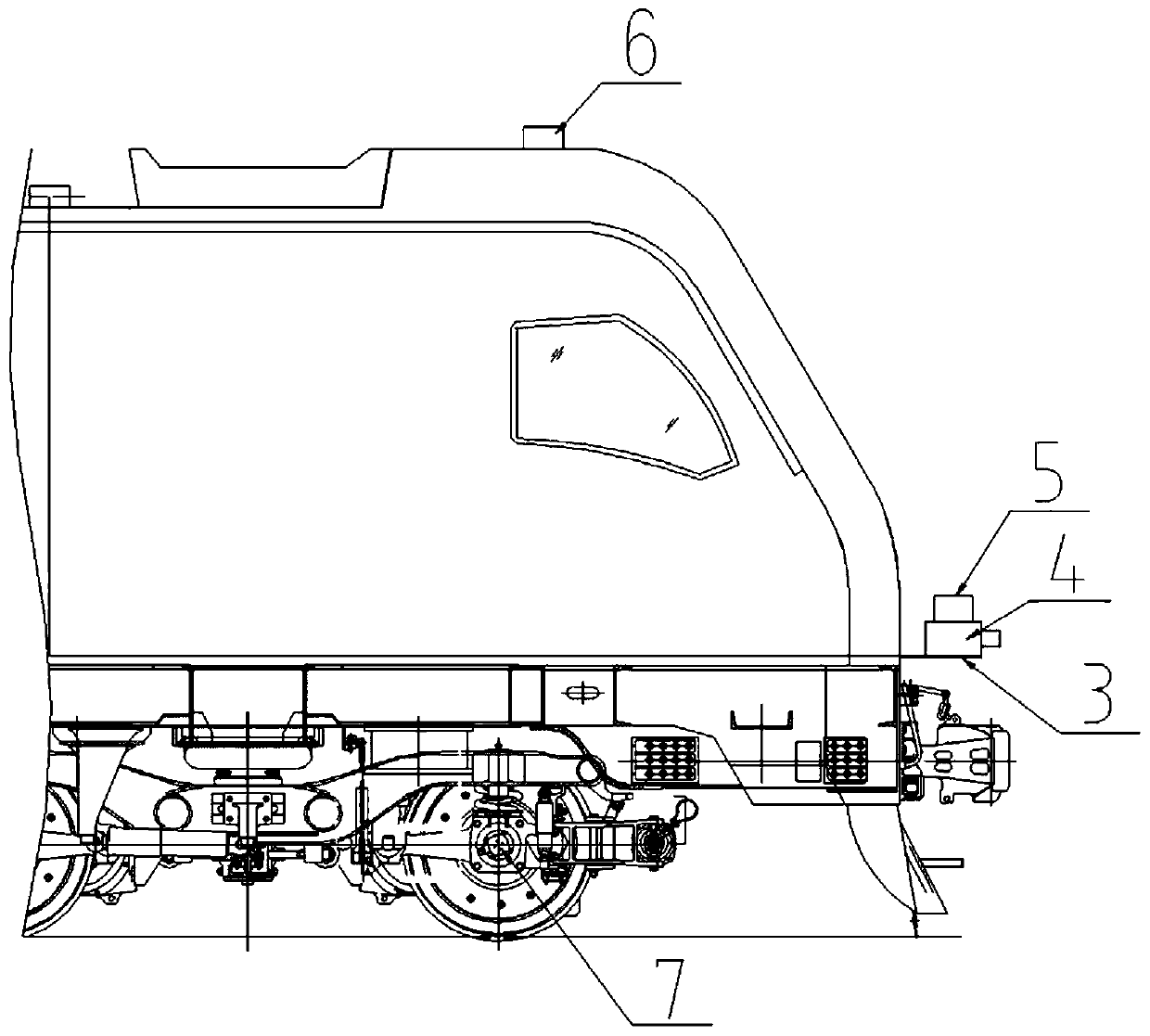
[0035] Reference Figure 1-3 , This embodiment provides a tunnel section and boundary scanning detection device, including:

[0036] The three-dimensional laser scanner 4 is fixedly installed on the front of the inspection vehicle 2 to obtain real-time profile data of the line;

[0037] The inertial navigation system 5 is fixedly connected to the three-dimensional laser scanner 4, and is used for real-time measurement of the pitch, roll, and headin...


PUM


Abstract

The invention relates to a tunnel section and boundary scanning and detecting device. The device comprises a 3D laser scanner for acquiring line section outline data in real time, an inertial navigation system fixedly connected with the 3D laser scanner and used for measuring pitching, rolling and heading angles of the moving 3D laser scanner in a spatial rectangular coordinate system in real time, a GPS antenna, an encoder, a data collection module collecting and storing data of the 3D laser scanner, the inertial navigation system, the GPS and the encoder in real time, and a data processor for acquiring data collected by the data collection module, processing the data and generating a 3D point cloud model, so as to analyze whether tunnel outline deformation and boundary meet design requirements. The invention further relates to a tunnel section and boundary scanning and detecting method. Through adoption of the method and device, the tunnel section and boundary are detected highly precisely in high-speed motion state, and the demand of tunnel general inspection of running high-speed railway is met.

Description

Technical field [0001] The invention relates to a tunnel detection equipment, in particular to a tunnel section and boundary scanning detection device and method. Background technique [0002] The tunnel building is an important part of the railway line, with high cost and relatively complicated structure. Due to the influence of geological structure and ground building activities, the tunnel building often undergoes structural changes, line deviations, etc., resulting in tunnel boundaries and contours Non-compliance with regulations endangers driving safety. At present, my country's high-speed railways are developing rapidly and the operating mileage continues to grow, which is in line with the closed line operation and skylight maintenance operation mode. Due to the busy operation, the skylight time left for the public works is relatively short, so that the traditional methods of tunnel contour and boundary detection using "rope", "stroke", "taper" and other means are low in e...

Claims


Application Information

Patent Timeline
Patent Type & Authority Applications(China)
IPC IPC(8): G01C7/06G01B11/24
CPCG01B11/24G01C7/06
Inventor 马文静袁玫竺箐刘伟瞿骥成
Owner CHINA RAILWAY ENG CONSULTING GRP CO LTD
Why Eureka
Try Eureka