
Antenna array with electrically adjustable inclination angle

An antenna array and sub-array technology, applied in the field of antenna arrays, can solve problems such as increased production costs, limited space for phase shifter layout, and increased precision requirements, to reduce size, improve production efficiency, and ensure consistent performance Effect

Pending Publication Date: 2019-07-12
GUANGDONG BROADRADIO COMM TECH
View PDF2 Cites 3 Cited by
  • Summary
  • Abstract
  • Description
  • Claims
  • Application Information

AI Technical Summary

Problems solved by technology

The solution is large in size and complex in structure, and it is difficult to layout in multi-system antennas
At present, the 5G standard Sub-6GHz frequency band is higher than the 4G system frequency band, and the spacing between the array unit groups is smaller, leaving very limited space for the layout of the phase shifter. It is difficult to miniaturize the size of the traditional electromechanical structure phase shifter. Breakthrough; at the same time, with the increase of frequency, the performance consistency of the phase shifter has higher requirements on the accuracy of the size of the cavity or pointer structure, the processing difficulty is very high, and the production cost rises sharply

Method used


Image

  • Antenna array with electrically adjustable inclination angle
  • Antenna array with electrically adjustable inclination angle
  • Antenna array with electrically adjustable inclination angle

Examples


Embodiment 1

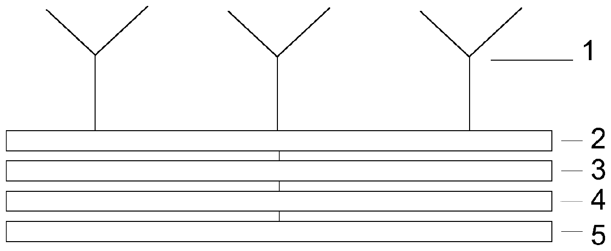
[0029] Such as figure 1 As shown, the present invention provides an antenna array with electrically adjustable inclination, which includes an array of antenna radiation elements 1 , multiple two-way power dividers 2 , multiple digital phase shifters 3 , a control circuit 4 and a power distribution network 5 .

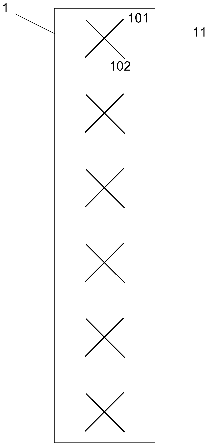
[0030] Specifically: the antenna radiating element array 1 includes a row of six dual-polarized radiating elements 11, such as figure 2 As shown, each dual-polarized radiating unit 11 is composed of a +45° polarized antenna unit 101 and a −45° polarized antenna unit 102 that are orthogonal to each other. The antenna radiating element array is made of plastic material integrated injection molding and then partial electroplating or printed circuit PCB etching electroplating. The element spacing of each antenna radiating element array is within the range of 0.5 to 0.8 times the wavelength of the central frequency of the working frequency band.

[0031] The same polariza...

Embodiment 2

[0042] The present invention provides another antenna array whose inclination angle can be adjusted electrically, which includes at least one sub-array with independent vertical plane inclination adjustment function, each sub-array includes an array of antenna radiation elements, multiple digital phase shifters, control circuits and power distribution network; the antenna radiating element array includes a row of multiple radiating elements; the digital phase shifter is in the form of a multi-phase shifter with constant phase offset, including an input end, an output end and a control end, the input end is connected to the output end of the power division network, and the output end The end is connected with the antenna radiation unit array, the control end is connected with the control circuit; the input end of the power dividing network is the radio frequency input port of the sub-array. Embodiment 2 is based on Embodiment 1, and does not include a two-way power divider, and ...


PUM


Abstract

The invention discloses an antenna array with an electrically adjustable inclination angle. The antenna array comprises at least one sub array having an independent vertical plane inclination angle adjusting function, and each sub array comprises an antenna radiation unit array, a plurality of power dividers, a plurality of digital phase shifters, a control circuit and a power distribution network; each antenna radiation unit array comprises a row of a plurality of radiation units, the output ends of the power dividers are connected with the same polarization of each two adjacent radiation units or each three adjacent radiation units; each digital phase shifter is a constant phase deviation multi-displacement phase shifter mode, and comprises an input end, an output end and a control end,the input ends are connected with the output end of a power division network, the output ends are connected with the input ends of the power dividers, and the control ends are connected with the control circuits; and the input end of the power division network is a radio frequency input ports of the sub arrays. The multi-band array antenna comprising a 5G system is high in part integration, smallin size and simple in assembling.

Description

technical field [0001] The invention relates to the technical field of communications, in particular to an antenna array with an electrically adjustable inclination angle. Background technique [0002] In a mobile communication system, the base station antenna uses a phase shifter to adjust the downtilt angle of the vertical plane to optimize the signal coverage of the cell. The input end of the phase shifter is connected to the radio frequency input port of the array antenna, and the multiple output ends of the phase shifter are connected to each radiation unit of the array antenna. The existing technology adopts the pointer type disclosed in the patent No. US6850130B1 or the cavity structure described in the patent No. CN104037475A, and adjusts the phase of the output end of the phase shifter through the sliding of the medium on the transmission line, thereby adjusting the phase of the array unit to achieve continuous downtilt angle adjust. [0003] The pointer-type or c...

Claims


Application Information

Patent Timeline
Patent Type & Authority Applications(China)
IPC IPC(8): H01Q21/08H01Q3/38
CPCH01Q21/08H01Q3/38
Inventor 吴泽海吴壁群苏振华
Owner GUANGDONG BROADRADIO COMM TECH
Learn More