
Large scale semi-rigid structure airship

A semi-rigid, large-scale technology, applied in the field of aerostats, can solve the problems of low stability and bearing capacity, unclear force transmission, and low rigidity of the stiffened ring tube, and achieve easy manufacturing and integration, low overall control difficulty, and flexibility Effect of load placement

Active Publication Date: 2019-07-16
SHANGHAI JIAO TONG UNIV +1
View PDF8 Cites 23 Cited by
  • Summary
  • Abstract
  • Description
  • Claims
  • Application Information

AI Technical Summary

Problems solved by technology

However, the rigidity of the stiffened ring tube of this structure is low and the stability is very poor. The long center shaft passes through the stiffened ring shaft from the beginning to the end respectively, which causes the center shaft to be subjected to a large bending force, which is easy to lose stability and load The force is low, the installation is inconvenient, and it is difficult to form an overall feasible pretension; the capsule and the structural system are difficult to cooperate with the force, and the overall structural efficiency is low
[0008] Wang Fei and Wang Weizhi proposed a semi-rigid system in "Semi-rigid stratospheric airship keel structure design and finite element analysis" (Aerospace Return and Remote Sensing, 2011, 32(4): 14-23.). The structure is not a self-supporting force system, and must be together with the capsule, which has poor integrity, and it is difficult for rigidity and flexibility to work together; the rigidity and bearing capacity of the ring frame are low; the main longitudinal beam is relatively large in compression, the ring frame is weakly constrained, and the force is complicated. The force transmission is not clear, its stability and bearing capacity are low

Method used


Image

  • Large scale semi-rigid structure airship
  • Large scale semi-rigid structure airship
  • Large scale semi-rigid structure airship

Examples


Embodiment Construction

[0031] The following describes several preferred embodiments of the present invention with reference to the accompanying drawings, so as to make the technical content clearer and easier to understand. The present invention can be embodied in many different forms of embodiments, and the protection scope of the present invention is not limited to the embodiments mentioned herein.

[0032] In the drawings, components with the same structure are denoted by the same numerals, and components with similar structures or functions are denoted by similar numerals. The size and thickness of each component shown in the drawings are shown arbitrarily, and the present invention does not limit the size and thickness of each component. In order to make the illustration clearer, the thickness of parts is appropriately exaggerated in some places in the drawings.

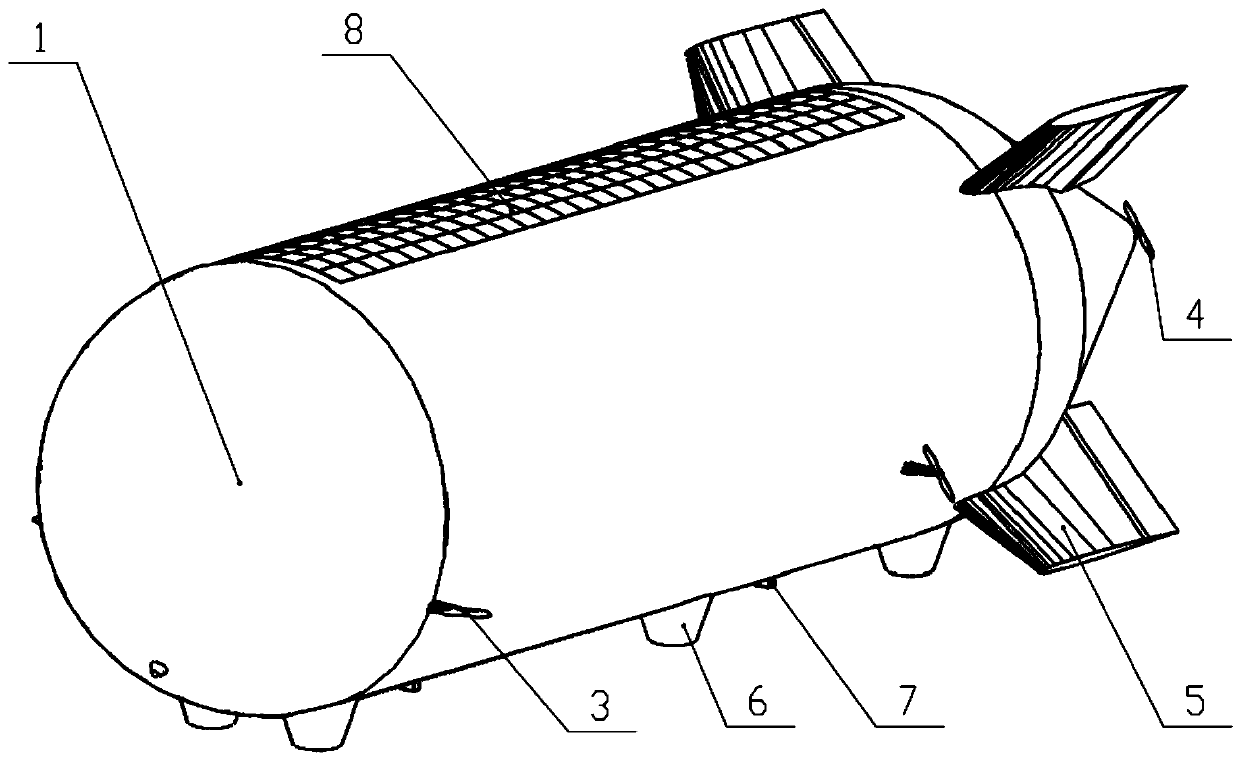
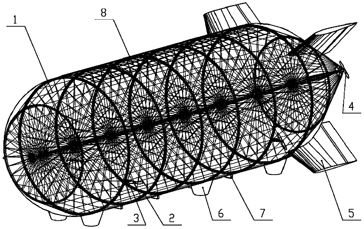
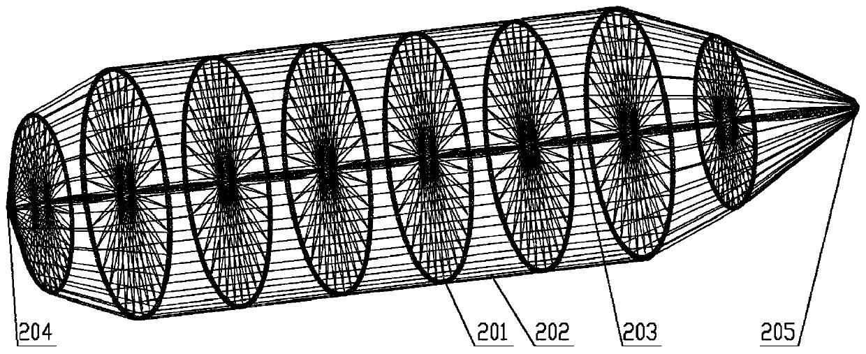
[0033] Such as figure 1 and figure 2As shown, this embodiment discloses a large-scale semi-rigid structure airship, including a ...


PUM


Abstract

The invention discloses a large scale semi-rigid structure airship, and relates to the technical field of floating air vehicles. The large scale semi-rigid structure airship includes a ship body, a vector side thrust, a vector tail thrust, an X-shaped inflatable tail fin, an air cushion and a pod, the ship body includes a pretension capsule and a tensegrity keel, the pretension capsule sleeves theouter surface of the tensegrity keel in a pretensioning mode, the vector side thrust is arranged on the lower-side part of the ship body, the vector tail thrust is arranged on the tail part of the ship body, the X-shaped inflatable tail fin is arranged on the tail part of the ship body in an X shape, the air cushion is arranged on the lower part of the ship body, and the pod is arranged on the lower part of the ship body. The airship adopts the structure of integrated and synergistic force bearing of an integral keel of a tension and compression self-balancing system and the pretension capsule, and has the characteristics of the integral conformity under the zero pressure of the capsule, the integral stiffness under the low pressure, high load bearing, flexible load arrangement and high-efficiency transfer.

Description

technical field [0001] The invention relates to the technical field of aerostats, in particular to a large-scale semi-rigid structure airship. Background technique [0002] The aeroplane is a light-than-air (Lighter-Than-Air, LTA) aircraft with power control and manoeuvrable maneuverability. It had a glorious history, but was later replaced by jet aircraft. With the development of new materials, power, energy, computers and other technologies, the special working principle and flight characteristics of airships have received attention and development in some specific application fields. [0003] Airship structures are often divided into soft, hard, and semi-rigid. Due to different structural systems, airships have different structural characteristics and flight characteristics, and have different applications. The blimp is light in weight, low in stiffness, and low in uneven load carrying capacity. Rigid airships are heavy, rigid and carry a large load, but they require la...

Claims


Application Information

Patent Timeline
Patent Type & Authority Applications(China)
IPC IPC(8): B64B1/08B64B1/20B64B1/24
CPCB64B1/08B64B1/20B64B1/24B64B1/30Y02T50/50B64D27/353B64B1/58
Inventor 陈务军付功义王晓亮王彦广王伟志徐建东汤令辰杨钧
Owner SHANGHAI JIAO TONG UNIV
Learn More