Biaxial tilting quad-rotor aircraft
A quad-rotor aircraft, the technology of the aircraft, applied in the direction of aircraft, unmanned aircraft, rotorcraft, etc., can solve the problems of increased body weight, complex structure, low lift and weight of multi-rotor aircraft, and reduced scale and size , the effect of wide application prospects
Pending Publication Date: 2019-07-16
FUZHOU UNIV
View PDF0 Cites 4 Cited by
- Summary
- Abstract
- Description
- Claims
- Application Information
AI Technical Summary
Problems solved by technology
The support arms and motor mounts of most traditional quadrotor aircraft are fixedly installed on the body. The four rotors of the aircraft rotate in the same plane. The rotors can only pitch and roll by changing the speed of the drive motor. Rotation and yaw movements require four variable speed drive motors and an adjustment control system, and the strain function is poor and the process is not stable enough. If the aircraft needs to complete the above three movements in time, the first method is to add Install a driver or install a driver and a tail pipe at the tail to meet the flight requirements
However, with the increase of equipment in this method, the weight of the body also increases, and more rotors or lengthened propellers are required to maintain the hovering motion of the aircraft. Although the method of increasing the rotors increases the reliability of the aircraft, the Its flexibility is difficult to guarantee
The second method is to use variable-pitch propellers. This method is based on trying to maintain the weight of the aircraft to maintain the high flexibility of the aircraft. However, this method requires a more complicated propeller and servo motor system, which is relatively difficult to implement. Complexity, high failure rate, and possible personal injury during failure
The above-mentioned methods for realizing the flexible flight movement of multi-rotor aircraft are either relatively low in lift and weight, or complex in structure and low in efficiency, which greatly restricts its wide application in various fields.
Method used
View moreImage
Smart ImageViewing Examples

Examples
Embodiment
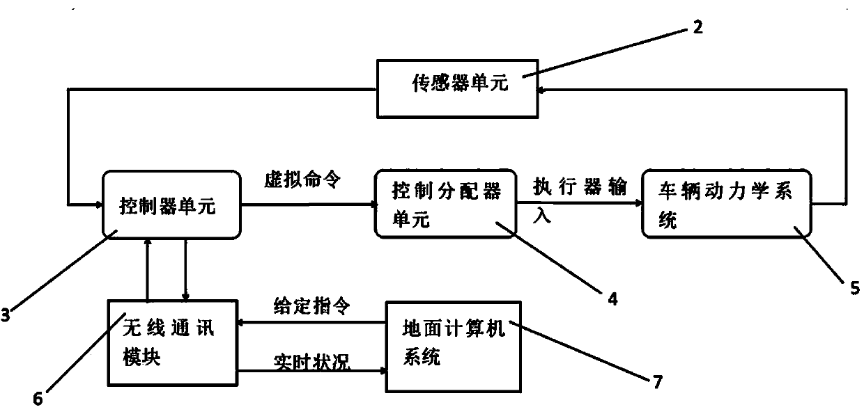
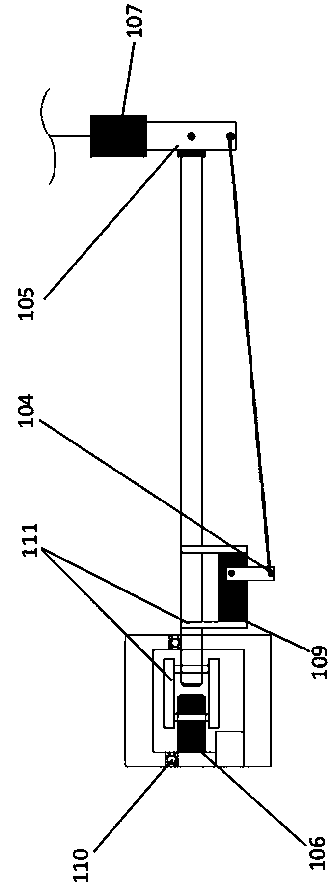
[0083] When the aircraft is changing its flight attitude, the controller unit controls the tilting mechanism, the servo motor drives the support arm to rotate so that the rotor tilts vertically in the direction perpendicular to the support arm, and the steering gear drives the motor holder to swing through the linkage mechanism to make the rotor rotate in the direction perpendicular to the support arm. The plane where the fuselage is located is tilted inward or outward, changing the lift output direction of the aircraft, and changing the flight attitude of the aircraft.
Login to View More PUM
 Abstract
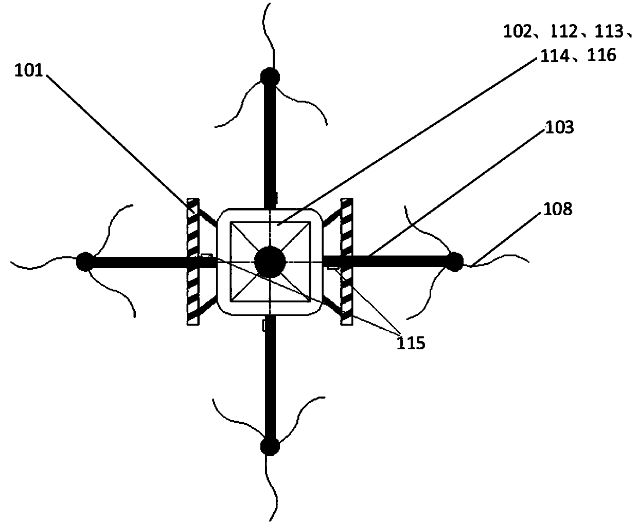
The invention provides a biaxial tilting quad-rotor aircraft. A fuselage includes a plurality of power arms, a sensor unit, a controller unit, a control distributor unit, a vehicle dynamics system module, and a wireless communication module, wherein the power arms are uniformly located at the periphery edge position of the fuselage, the sensor unit, the controller unit, the control distributor unit, the vehicle dynamics system module, and the wireless communication module are arranged at the fuselage position; the wireless communication module can establish wireless communication with a groundcontrol station; the power arms comprise rotor wings and inclined mechanisms; rotor swings are driven by drive motors at motor fixing seats supported by the inclined mechanisms; the inclined mechanisms are connected with the controller unit; and the controller unit adjusts the positions and orientation of the rotor wings by the inclined mechanisms to adjust flight of the aircraft. According to the biaxial tilting quad-rotor aircraft, the rotation speed and the inclined rotating angle of the four rotor wings can be automatically adjusted according to an input instruction, stability of a systemis controlled by a closed-loop, the flight status of the aircraft is fed back, self flight adjusting and control work is automatically completed, and the purposes of flight pitching, rolling and yaware achieved; and the high efficiency and high reliability of flight adjusting control are ensured.
Description
technical field [0001] The invention relates to the technical field of small unmanned aerial vehicles, in particular to a dual-axis inclined quadrotor aircraft. Background technique [0002] The dual-axis tilting rotor configuration refers to the rotor configuration in which the rotation plane of the rotor forms a certain angle with the plane of the body through the rotation of the support arm and the motor holder. Since the aircraft has the characteristics of dual-axis tilting, the rotor of the aircraft The effect of tilting around the driving motor can be achieved, and it is easy to perform pitch, roll and yaw movements, so as to realize the purpose of flexible flight of the aircraft. The support arms and motor mounts of most traditional quadrotor aircraft are fixedly installed on the body. The four rotors of the aircraft rotate in the same plane. The rotors can only pitch and roll by changing the speed of the driving motor. Rotation and yaw movements require four variabl...
Claims
Login to View More Application Information
Patent Timeline
 Patent Type & Authority Applications(China)
IPC IPC(8): B64C27/08B64C27/52H04W76/10G08C17/02G05D1/08
CPCG05D1/0825B64C27/08B64C27/52H04W76/10G08C17/02B64U10/10
Inventor 雷瑶叶艺强王金利
Owner FUZHOU UNIV