Electronic equipment shell, manufacturing method thereof and electronic equipment

A technology for electronic equipment and casings, applied in metal material coating process, fusion spraying, coating and other directions, can solve the problems of inability to make complex 3D structures, poor wear resistance of mobile phone casings, etc., to achieve high market competitiveness, high resistance to The effect of high drop performance and easy operation

Inactive Publication Date: 2019-07-16
GUANGDONG OPPO MOBILE TELECOMM CORP LTD
View PDF3 Cites 6 Cited by
  • Summary
  • Abstract
  • Description
  • Claims
  • Application Information

AI Technical Summary

Problems solved by technology

[0002] The existing metal mobile phone frames or shells are often made of deformed aluminum alloy, die-cast aluminum alloy, stainless steel and other materials, but these metal mobile phone shells have the problem of poor wear resistance
Ceramics have jade-like luster and smooth feel, high wear resistance and high hardness, making the middle frame or shell of ceramic mobile phones made of ceramics not easy to be scratched, but ceramics also have the disadvantage of not being able to make complex 3D structures.

Method used


Image

  • Electronic equipment shell, manufacturing method thereof and electronic equipment
  • Electronic equipment shell, manufacturing method thereof and electronic equipment
  • Electronic equipment shell, manufacturing method thereof and electronic equipment

Examples


Embodiment 1

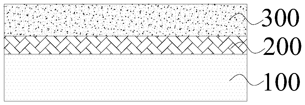
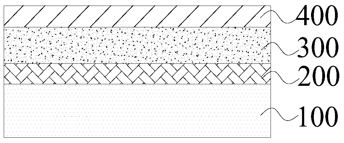
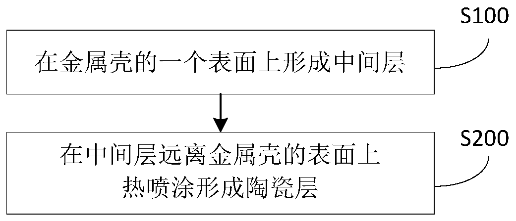
[0062] In this embodiment, the metal alloy is first primed on the surface of the metal layer, and then the ceramic layer is formed by thermal spraying. Among them, Al (type 6061) material is selected for the metal layer, and an intermediate layer of Ni-5w / w% Al is formed by arc spraying on the surface of the aluminum substrate, and then Al is formed on the surface of the aluminum substrate by plasma spraying. 2 o 3 ceramic layer.

[0063] Al of this example 2 o 3 The Ni-5w / w%Al intermediate layer added between the ceramic layer and the aluminum substrate has a binding force test result of 18-23MPa. Compared with Comparative Example 1, the interlayer bonding force can be doubled.

Embodiment 2

[0068] In this embodiment, the metal alloy is first primed on the surface of the metal layer, and then the ceramic layer is formed by thermal spraying. Among them, Al (type 6061) material is selected for the metal layer, and an intermediate layer of Ni-15w / w% Al is formed by arc spraying on the surface of the aluminum substrate, and then Al is formed on the surface of the aluminum substrate by plasma spraying. 2 o 3 -TiO 2 ceramic layer.

[0069] Al of this example 2 o 3 -TiO 2 The Ni-15w / w%Al intermediate layer added between the ceramic layer and the aluminum substrate has a binding force test result of 19-23MPa. Compared with Comparative Example 2, the intermediate layer can increase the interlayer bonding force by about 1 time.

Embodiment 3

[0074]In this embodiment, the metal alloy is first primed on the surface of the metal layer, and then the ceramic layer is formed by thermal spraying. Among them, the metal layer is made of stainless steel (model SUS304), and an intermediate layer of Ni-10w / w% Co is first formed on the surface of the stainless steel substrate, and then WC-10Co-4Cr is formed on the surface of the stainless steel substrate by supersonic flame spraying ceramic layer.

[0075] The interlayer added between the WC-10Co-4Cr ceramic layer and the stainless steel substrate in this embodiment has a bonding force test result of 65-75 MPa. Compared with Comparative Example 3, the intermediate layer can increase the interlayer bonding force by about 50%.


PUM

PropertyMeasurementUnit
thicknessaaaaaaaaaa
thicknessaaaaaaaaaa
thicknessaaaaaaaaaa

Abstract

The invention provides an electronic equipment shell, a manufacturing method thereof and electronic equipment. The electronic equipment shell comprises a metal layer, a middle layer and a ceramic layer, wherein the middle layer is arranged on one surface of the metal layer and is formed by a metal alloy; and the ceramic layer is arranged on the surface, far away from the metal layer, of the middlelayer. According to the electronic equipment shell, the middle layer of the metal alloy is additionally arranged between the metal layer and the ceramic layer, so that the bonding force between the metal layer and the ceramic layer can be effectively increased, the metal layer has the appearance, the texture, the high hardness and the wear resistance of ceramic, and meanwhile, the electronic equipment shell has higher anti-falling performance.

Description

technical field [0001] The present invention relates to the technical field of shell production of electronic equipment, and in particular, the present invention relates to a shell of electronic equipment, a manufacturing method thereof, and electronic equipment. Background technique [0002] The existing metal mobile phone frames or shells are often made of deformed aluminum alloy, die-cast aluminum alloy, stainless steel and other materials, but these metal mobile phone shells have the problem of poor wear resistance. Ceramics have jade-like luster and smooth feel, high wear resistance and high hardness, making the middle frame or shell of ceramic mobile phones made of ceramics not easy to be scratched, but ceramics also have the disadvantage of not being able to make complex 3D structures. Contents of the invention [0003] An object of the embodiments of the present invention is to provide a casing for an electronic device, a method for manufacturing the casing by sequ...

Claims


Application Information

Patent Timeline
Patent Type & Authority Applications(China)
IPC IPC(8): C23C4/131C23C4/129C23C4/134C23C4/10C23C4/11C23C4/08
CPCC23C4/08C23C4/10C23C4/11C23C4/129C23C4/131C23C4/134
Inventor 杨光明
Owner GUANGDONG OPPO MOBILE TELECOMM CORP LTD
Why Eureka
Try Eureka