Foam drainage gas production method, device and system
A technology of foam drainage and gas recovery, which is applied in the direction of mining fluid, earthwork drilling, measurement, etc., can solve the problems such as the inability to quantitatively add chemicals, and achieve the effects of reducing production costs and improving drainage efficiency
- Summary
- Abstract
- Description
- Claims
- Application Information
AI Technical Summary
Problems solved by technology
Method used
Image

Examples
Embodiment 1
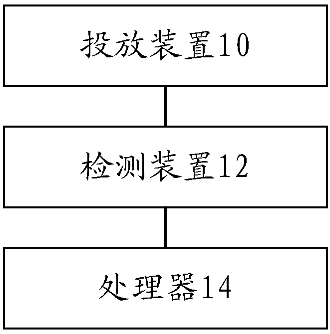
[0031] The embodiment of the present invention provides a foam drainage gas recovery system, figure 1 It is a schematic block diagram of a foam drainage gas recovery system according to an embodiment of the present invention, such as figure 1 As shown, the foam drainage gas recovery system includes: a delivery device 10, a detection device 12 and a processor 14, wherein,
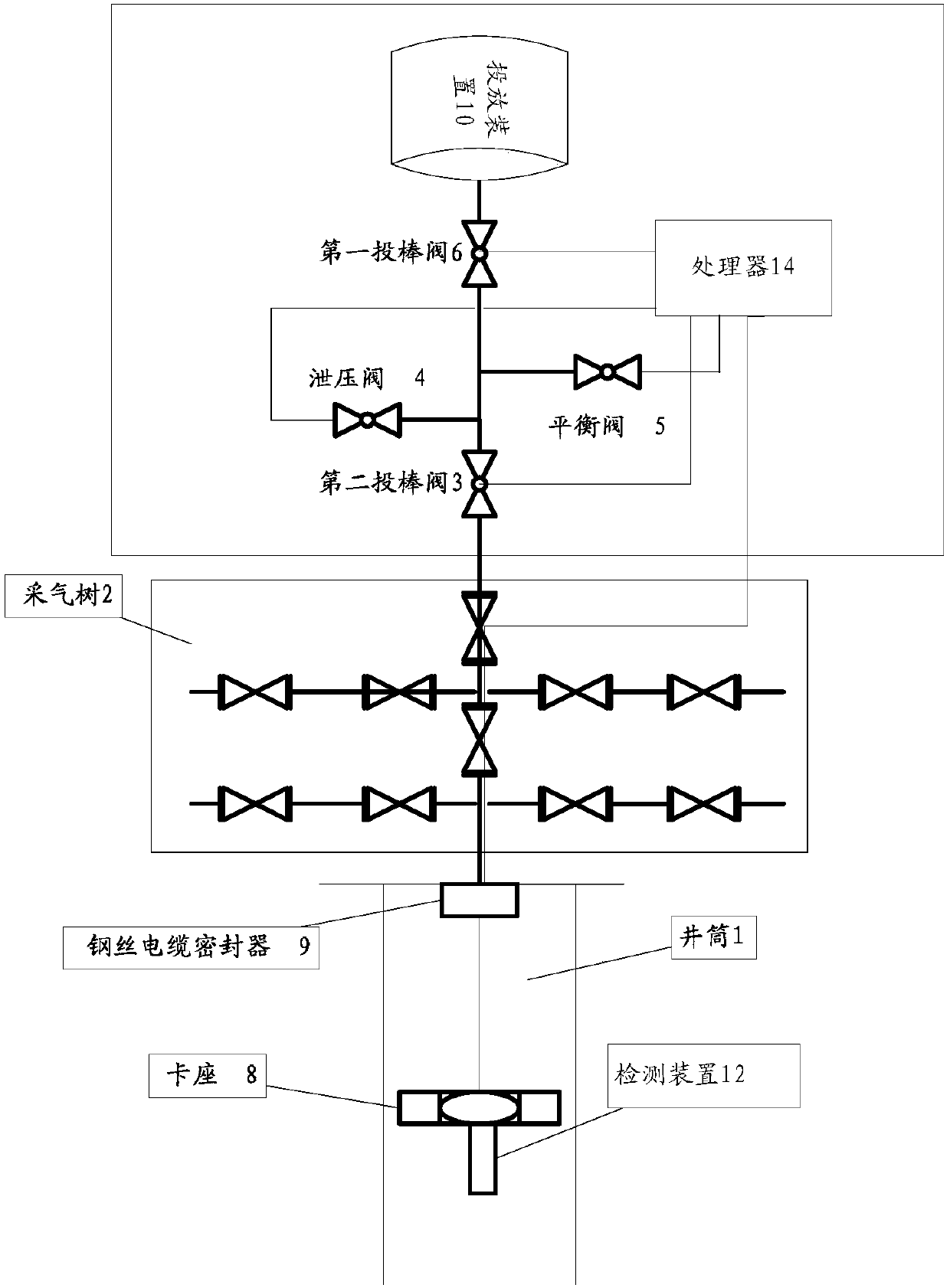
[0032] The delivery device 10 is set on the foam drainage and gas recovery system, wherein the delivery device is provided with an accommodation space inside, and the accommodation space is used for accommodating foam row rods; the detection device 12 is arranged inside the downhole space, and is used to detect the above-mentioned downhole space The pressure value; the processor 14 is connected with the above-mentioned detection device 12 and the above-mentioned delivery device 10, and is used to determine the liquid accumulation height of the above-mentioned downhole space according to the pressure value dete...
Embodiment 2
[0063] The embodiment of the present invention provides a method embodiment of a foam drainage gas recovery method. It should be noted that the steps shown in the flow chart of the accompanying drawings can be executed in a computer system such as a set of computer-executable instructions, and , although a logical order is shown in the flowcharts, in some cases the steps shown or described may be performed in an order different from that shown or described herein.
[0064] Figure 4 It is a flow chart of the steps of a foam drainage gas recovery method according to an embodiment of the present invention, such as Figure 4 As shown, the method includes the following steps:
[0065] Step S102, acquiring the pressure value of the downhole space detected by the detection device;
[0066] Step S104, determining the fluid accumulation height of the above-mentioned downhole space according to the pressure value of the above-mentioned downhole space;
[0067] Step S106, generating ...
Embodiment 3
[0078] The embodiment of the present invention also provides another foam drainage and gas collection system, including: a dispensing device, which is arranged on the foam drainage and gas collection system, wherein the interior of the dispensing device is provided with an accommodation space, and the accommodation space is used to accommodate foam discharge rods The detection device is arranged inside the downhole space and is used to detect the liquid accumulation height of the above-mentioned underground space; the processor is connected with the above-mentioned detection device and the above-mentioned dispensing device, and is used to generate the above-mentioned liquid accumulation height according to the above-mentioned liquid accumulation height of the above-mentioned underground space. A control instruction corresponding to the height, wherein the control instruction is used to control the delivery device to inject the foam discharge rod corresponding to the height of th...
PUM
 Abstract
Description
Claims
Application Information
 - R&D
- Intellectual Property
- Life Sciences
- Materials
- Tech Scout
- Unparalleled Data Quality
- Higher Quality Content
- 60% Fewer Hallucinations
Browse by: Latest US Patents, China's latest patents, Technical Efficacy Thesaurus, Application Domain, Technology Topic, Popular Technical Reports.
© 2025 PatSnap. All rights reserved.Legal|Privacy policy|Modern Slavery Act Transparency Statement|Sitemap|About US| Contact US: help@patsnap.com