Integrated deep removal device of dioxin and dust in flue gas

A technology for removing flue gas, applied in gas treatment, transportation and packaging, chemical instruments and methods, etc., can solve the problems of complex flue gas composition, troublesome management and operation, and aggravated material matching, so as to facilitate transportation and on-site installation , worry-free management and operation, and the effect of reducing the burden on the enterprise

Pending Publication Date: 2019-07-19
NANJING INST OF ENVIRONMENTAL SCI MINIST OF ECOLOGY & ENVIRONMENT OF THE PEOPLES REPUBLIC OF CHINA
View PDF3 Cites 0 Cited by
  • Summary
  • Abstract
  • Description
  • Claims
  • Application Information

AI Technical Summary

Problems solved by technology

First, there are fluctuations in the flue gas working conditions, and the material matching system relies on the measurement of the flue gas probe. Once the flue gas flow rate is too high, the material matching system will produce time lag
Moreover, according to the investigation of the inventor, due to various limitations of the existing devices, the probe cannot be installed far enough from the activated carbon injection port, and if the probe is close to the injection port, the material matching lag will be further aggravated
Second, due to the complex composition of the flue gas, the probe is prone to wear and corrosion, which leads to inaccurate measurement data of the probe, which in turn leads to the failure of the material matching system, making the flue gas treatment unable to meet the standard, and replacing the probe will increase the cost
Third, the use of activated carbon particles for adsorption requires supporting activated carbon storage tanks, lifting devices, injection devices and other equipment. There are many equipments, resulting in a large area of ​​the removal device, high cost, and troublesome management and operation.

Method used


Image

  • Integrated deep removal device of dioxin and dust in flue gas
  • Integrated deep removal device of dioxin and dust in flue gas
  • Integrated deep removal device of dioxin and dust in flue gas

Examples


Embodiment Construction

[0026] In order to enable those skilled in the art to better understand the solution of the present invention, the integrated deep removal device for flue gas dioxin and dust of the present invention will be further described in detail below with reference to the drawings and specific embodiments.

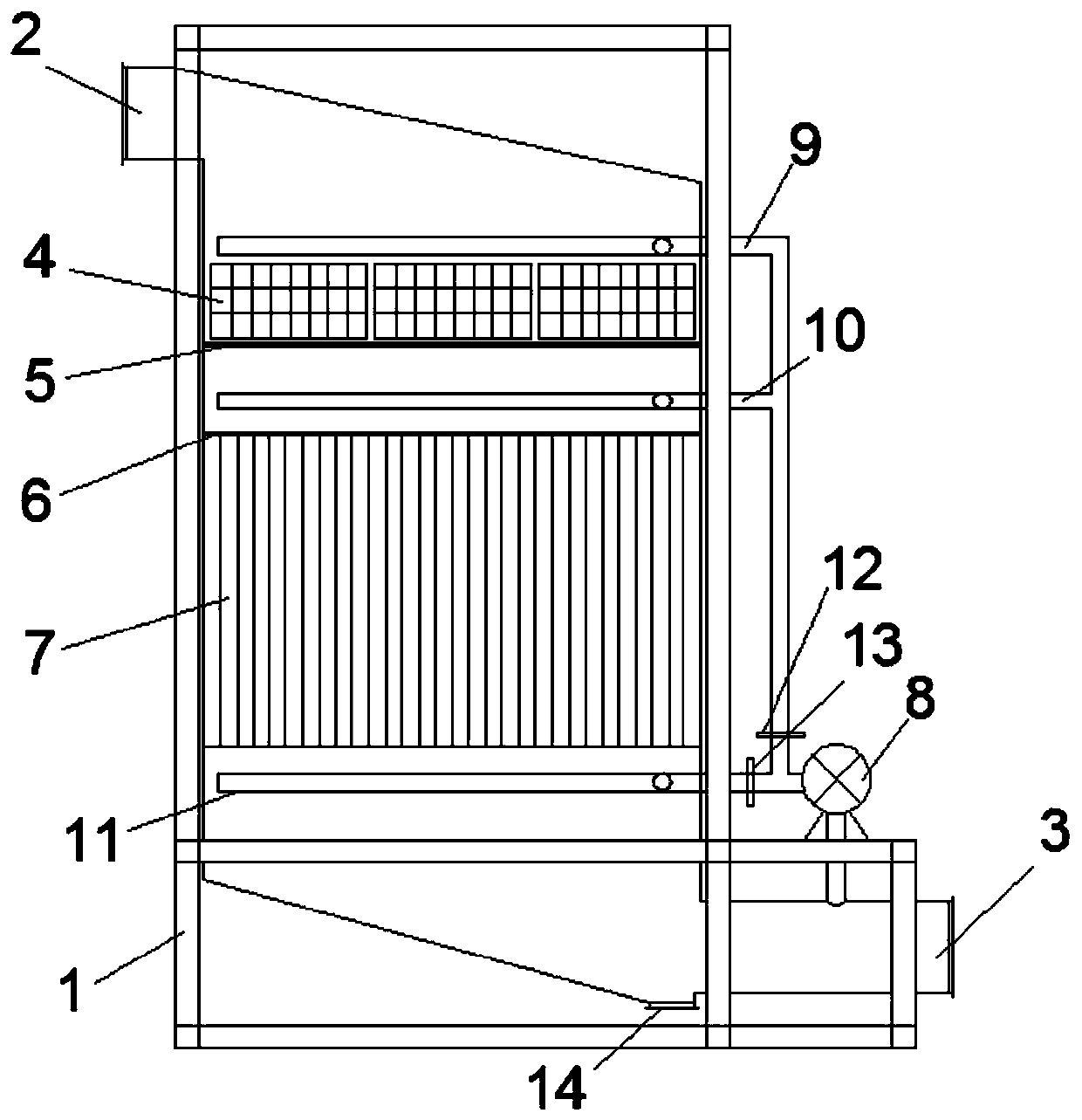
[0027] Such as figure 1 The shown flue gas dioxin and dust integrated deep removal device includes a box body 1, an induced draft fan 8, and a flue gas inlet 2, which is arranged in sequence from top to bottom in the box body 1, a removal device body and flue gas Exit 3. The flue gas inlet 2 is welded and connected to the upper part of the removal device body, and the flue gas outlet 3 is welded and connected to the lower part of the removal device body. The removal device body is fixed by a joist preset on the frame of the box 1, and the removal device body is connected to The joist is welded.

[0028] Activated carbon bracket 5 and bag suspension beam 6 are successively fixed on the ...


PUM


Abstract

The invention discloses an integrated deep removal device of dioxin and dust in flue gas and belongs to the field of environmental protection. The removal device is in an integral structure and comprises a case body, wherein a flue gas inlet, a removal device body and a flue gas outlet are formed and arranged in the case body from the top down. An active carbon bracket and a bag hanging beam are sequentially fixed in the removal device body in a flue gas flow direction; massive honeycomb active carbon in a quantity matched with a maximum working condition flue gas amount is arranged on the active carbon bracket; and dedusting bags are fixed below the bag hanging beam. A sealing door is arranged on the front end face of the removal device body and located at the honeycomb active carbon, andthe honeycomb active carbon can be replaced when the sealing door is opened. According to the device, an active carbon particle spray system is replaced by the massive honeycomb active carbon in thequantity matched with the maximum working condition flue gas amount; failure in effective removal of dioxin can be effectively avoided when a flue gas working condition fluctuates; and the device is high in reliability and has the advantages of small floor area, low cost and the like.

Description

Technical field [0001] The invention belongs to the field of environmental protection, and relates to an integrated deep removal device for flue gas dioxin and dust. Background technique [0002] The incineration of hazardous waste will produce pollution factors such as nitrogen oxides, dust, sulfur dioxide, and dioxins. Among them, dioxins are the key indicators. Dioxins are highly toxic. The compounds they contain have a high melting point, are not active, are hardly soluble in water, have strong chemical stability, and can exist for a long time in the environment. The International Center for Cancer Research has listed dioxin as a first-level human carcinogen. Even in small amounts, long-term intake is very likely to induce cancer. [0003] As the country strengthens its management of hazardous wastes, more and more hazardous wastes need to be disposed of through incineration processes. In order to reduce environmental pollution and improve environmental quality, the state has...

Claims


Application Information

Patent Timeline
Patent Type & Authority Applications(China)
IPC IPC(8): B01D53/04B01D46/30B01D46/02B01D46/00
CPCB01D46/30B01D46/023B01D46/0002B01D46/0036B01D53/04B01D2257/2064B01D46/62
Inventor 刘景龙严小飞张强孙孜菲孙聪聪
Owner NANJING INST OF ENVIRONMENTAL SCI MINIST OF ECOLOGY & ENVIRONMENT OF THE PEOPLES REPUBLIC OF CHINA
Why Eureka
Try Eureka