
Abrasive water jet cutting nozzle and application thereof

A technology of abrasive water jet and spray head, which is applied in the direction of abrasives, abrasive feeding devices, spray guns, etc., can solve the problems of continuous operation, segmental milling, and increased cost of use, so as to improve cutting efficiency and facilitate The effect of production, ease of assembly

Active Publication Date: 2019-07-19
CHONGQING UNIV
View PDF8 Cites 2 Cited by
  • Summary
  • Abstract
  • Description
  • Claims
  • Application Information

AI Technical Summary

Problems solved by technology

However, their research and equipment are mainly used in offshore oil well casing cutting, which can only cut the tubing, but not milling in segments; using pre-mixed abrasive water jets to add abrasives must release pressure, and continuous work cannot be guaranteed during operation; abrasives , Water consumption is large, not suitable for remote or water-scarce land areas
In addition, in order to ensure the effective coverage of the cutting section, the existing nozzles need to rotate to work, and an additional device for driving the rotation of the nozzles is required, which increases the cost of use

Method used


Image

  • Abrasive water jet cutting nozzle and application thereof
  • Abrasive water jet cutting nozzle and application thereof
  • Abrasive water jet cutting nozzle and application thereof

Examples


Embodiment Construction

[0026] The present invention will be described in detail below in conjunction with the accompanying drawings.

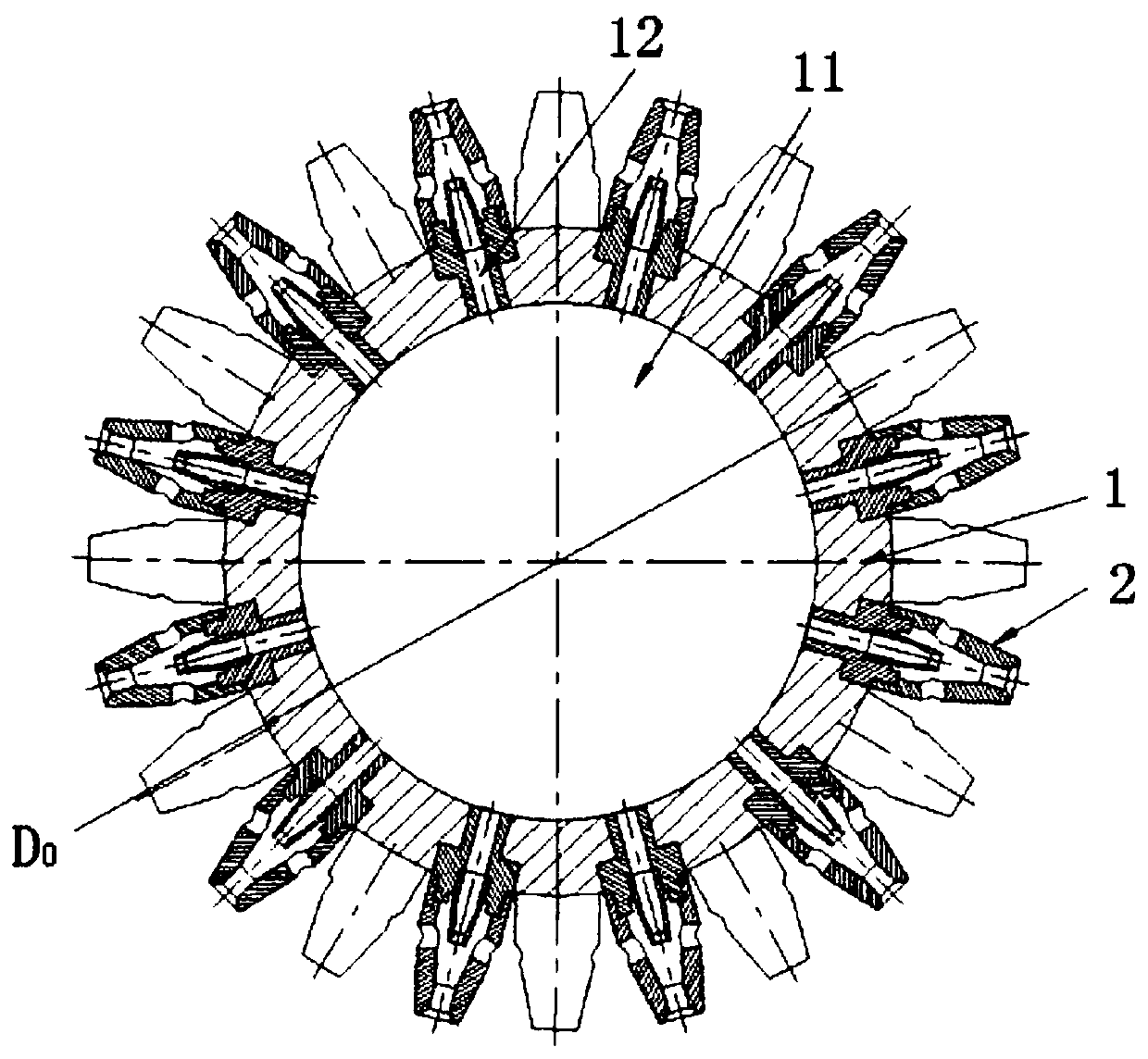
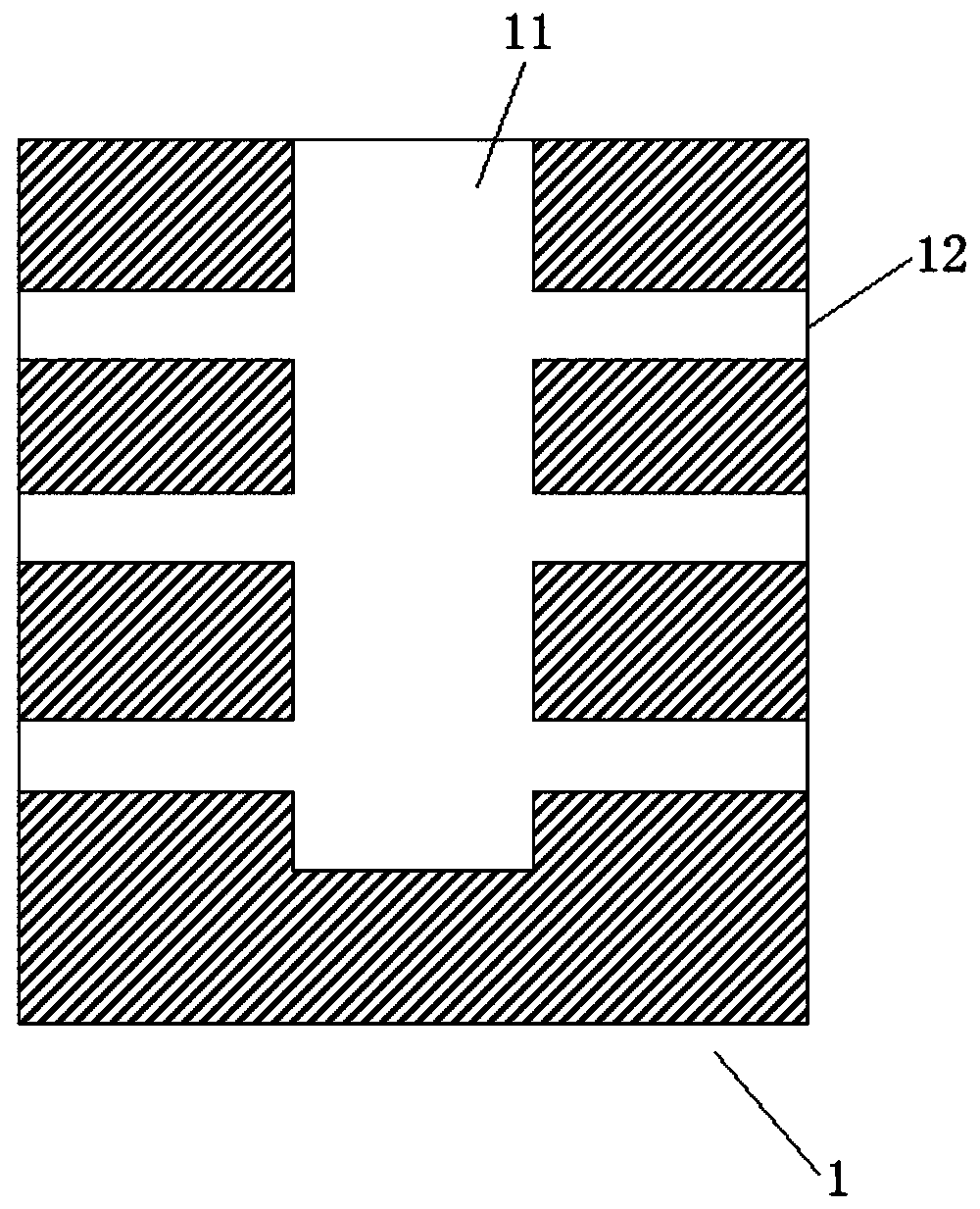
[0027] see Figure 1 to Figure 5 , the abrasive water jet cutting nozzle shown includes a nozzle body 1, the nozzle body 1 is provided with axial blind holes 11, and on multiple radial planes of the nozzle body 1, a plurality of axial The nozzle holes 12 connected to the blind holes 11 are arranged alternately on adjacent radial planes, and each nozzle hole 12 is provided with a nozzle 2 . The setting of the axial blind hole 11 ensures that the fluid can enter the nozzle 2 from the radial direction, so that the movement direction of the fluid is perpendicular to the axis of the nozzle body 1, thereby realizing the radial cutting of the downhole casing.

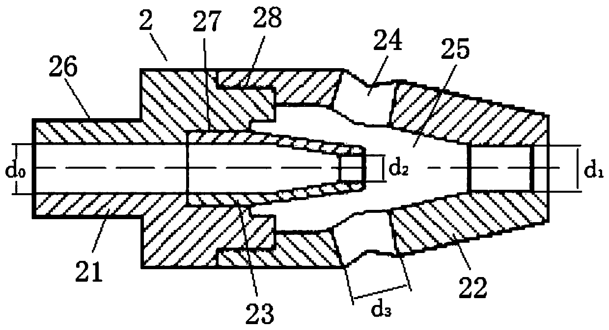
[0028] The nozzle 2 includes a coaxially arranged base 21, an outer nozzle 22 and an inner nozzle 23, the base 21 is provided with an axial through hole, one end is provided with a first external thread 26 connected...


PUM


Abstract

The invention discloses an abrasive water jet cutting nozzle and an application thereof. The abrasive water jet cutting nozzle comprises a nozzle body, wherein the nozzle body is provided with an axial blind hole, a plurality of nozzle holes communicated with the axial blind holes are uniformly distributed in the radial planes of the nozzle body in the radial direction, the nozzle holes in the adjacent radial surfaces are arranged in a staggered mode, a nozzle is arranged in each nozzle hole, the nozzle comprises a base arranged coaxially, an outer nozzle and an inner nozzle, the base is provided with an axial through hole, one end of the base is connected with the nozzle hole, the other end of the outer nozzle is connected with an outer nozzle and an inner nozzle, the inlet end of the outer nozzle is connected with the outer edge of the end surface of the base, and the base, a plurality of suction inlets communicated with the mixing chamber are formed in the side wall of the outer nozzle in the radial direction, the inner nozzle is arranged in the mixing chamber, the inlet end of the inner nozzle is connected with the center of the end surface of the base, and the outlet end of the inner nozzle is communicated with the mixing chamber. So that the recycling of the grinding materials can be realized, the cost is reduced, the device is suitable for remote mountainous areas whichare inconvenient to transport, and the practicability is high.

Description

technical field [0001] The invention relates to abrasive water jet technology, in particular to an abrasive water jet cutting nozzle and its application. Background technique [0002] In recent years, with the rapid development of our society, the demand for oil and natural gas resources has become greater and greater, and the exploitation efforts have also increased. With the increase of oil and natural gas mining time and the depletion of local oil and gas resources, more and more Oil and gas wells are approaching their service life and have lost their value for continued use, and oil and gas wells have also completed their missions. In order to prevent oil and gas pollution, for the oil and gas wellheads that have reached the service life, they need to be abandoned in accordance with national regulations to seal the oil and gas wells. However, sealing the wellheads cannot achieve the desired effect. It is necessary to drill and mill a space below the wellhead. For better...

Claims


Application Information

Patent Timeline
IPC IPC(8): B24C5/04B24C7/00
CPCB24C5/04B24C7/0007
Inventor 汤积仁卢义玉夏彬伟李国葛兆龙汪壘刘辉张洋凯
Owner CHONGQING UNIV
Learn More