Supercharge Your Innovation With Domain-Expert AI Agents!

Calibration method for spatial position of laser beam

A calibration method and laser beam technology, applied in the direction of using optical devices, measuring devices, instruments, etc., can solve the problems of inability to determine the spatial position, not suitable for wide application, etc., and achieve the effect of simple method

Active Publication Date: 2019-07-19
TIANJIN UNIV
View PDF11 Cites 4 Cited by
  • Summary
  • Abstract
  • Description
  • Claims
  • Application Information

AI Technical Summary

Problems solved by technology

[0004] Related Papers (①Bi Chao, Fang Jianguo, Liu Jingliang, Liu Yong, Li Chengwei. Beam Direction Calibration of Laser Displacement Sensor Based on Spherical Target[J]. Optical Precision Engineering, 2015,23(3):678-685; ②JunhuaSun, JieZhang ,ZhenLiuand GuangjunZhang.Avisionmeasurementmodelolaserdisplacementsensoranditscalibrationmethod[J].Optics&LasersinEngineering,2013,51(12):1344-1352.) proposed a laser beam calibration method, but only the direction vector of the laser beam is calibrated, and its spatial position cannot be determined, if Strict requirements on experimental equipment are not suitable for widespread use. Therefore, it is necessary to continue to study the calibration method of laser beams

Method used


Image

  • Calibration method for spatial position of laser beam
  • Calibration method for spatial position of laser beam
  • Calibration method for spatial position of laser beam

Examples


Embodiment Construction

[0019] The present invention will be further described below in conjunction with the accompanying drawings.

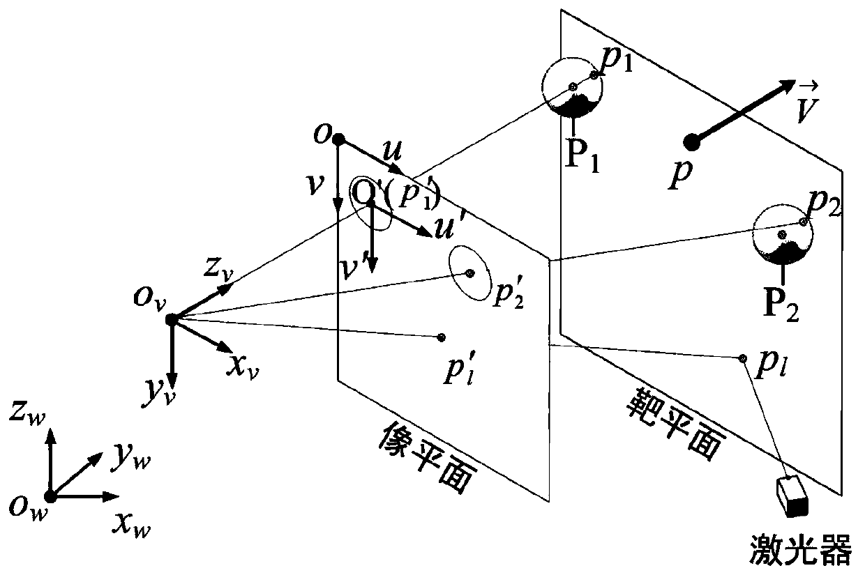
[0020] Such as figure 1 As shown, the point p on the target plane 1 ,p 2 ,p l are projected onto the image plane as points p 1 ', p' 2 ,p l '.

[0021] In order to express more clearly, the coordinate representation of each point in each coordinate system is shown in Table 1:

[0022] Table 1

[0023]

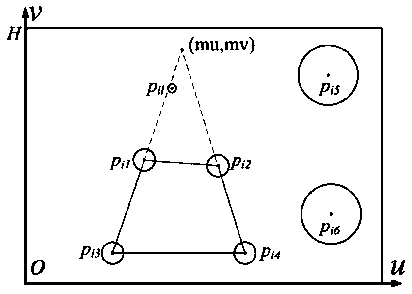
[0024] (1) A camera with a telecentric lens and a target plane are used to build a laser beam calibration device. The camera is facing the target plane. Two target spheres and four equal-diameter shadow circles are set on the target plane. There is no special requirement for their position distribution. It only needs to meet the line connecting the center of the shadow circle to form a square, and both the target ball and the shadow circle are within the field of view of the camera;

[0025] (2) Take the coordinate system of the three-coordinate measuring ma...


PUM


Abstract

The invention provides a calibration method for a spatial position of a laser beam. The calibration method comprises the following steps: forming a laser beam calibration device by adopting a target plane and a camera provided with a telecentric lens, wherein the camera is dead against the target plane, and two target balls and four isodiametric shadow circles are arranged on the target plane; taking a coordinate system of a three coordinate measuring machine as a world coordinate system, measuring parameters of the target plane by utilizing the three coordinate measuring machine, and obtaining a normal vector of the target plane and coordinates of any point on the target plane; calculating coordinates of a projective point of the center of each target ball on the target plane; establishing a viewpoint coordinate system; acquiring an image of the target plane by utilizing the camera, and extracting a laser point, circle centers of projections of the target balls as well as pixel coordinates of circle centers of the four shade circles by virtue of a centroid method, so that the circle centers of the four shade circles are taken as control points for perspective correction of the image; establishing a relationship between coordinates of a spatial point and coordinates of projection of the spatial point in a projection plane; obtaining three-dimensional spatial coordinates of thelaser point in the world coordinate system; and fitting the spatial position of the laser beam.

Description

technical field [0001] The invention relates to a precision measurement system, in particular to a method for calibrating the space pose of a laser beam in a coordinate measurement system constructed by a laser and an electric control rotary table. Background technique [0002] In order to complete the non-contact three-dimensional coordinate measurement, the laser is combined with the electric control rotary table to build a coordinate measurement system based on angle-angle intersection. This system is similar to theodolite measurement system and consists of two measurement units, each of which is composed of It consists of two independent one-dimensional electronically controlled rotating stages and a laser. When assembling the measurement unit, the "three-axis" structure proposed by the patent application (based on the measurement method of the non-orthogonal axis laser theodolite, 201410850221.8) is adopted, and the two rotating platforms are respectively named as the h...

Claims


Application Information

Patent Timeline
IPC IPC(8): G01B11/00
CPCG01B11/005
Inventor 吴斌张振康杰虎段晓登薛婷
Owner TIANJIN UNIV
Features
  • R&D
  • Intellectual Property
  • Life Sciences
  • Materials
  • Tech Scout
  • Unparalleled Data Quality
  • Higher Quality Content
  • 60% Fewer Hallucinations
Learn More