Direct measurement method of geogrid force based on fiber bragg grating technology

A geogrid and fiber grating technology, which is used in water conservancy, civil engineering monitoring, electric power, and transportation fields, can solve the problems that the traditional sensor sensing accuracy is difficult to meet the requirements, a more accurate conclusion cannot be drawn, and the force value cannot be obtained. , to avoid the influence of wavelength reflection, avoid changes in strength and reinforcement properties, and improve interface compatibility

Active Publication Date: 2019-07-19
SHANGHAI UNIV
View PDF7 Cites 1 Cited by
  • Summary
  • Abstract
  • Description
  • Claims
  • Application Information

AI Technical Summary

Problems solved by technology

However, due to the lack of effective tools to help experimental research on the deformation and stress value of reinforced materials such as geogrids during the reinforcement process, no more accurate conclusions have been drawn so far.
For the measurement of geogrid deformation and force, in the indoor model test of civil engineering, the deformation is relatively small, and the sensing accuracy of traditional sensors is difficult to meet the requirements; when applied in actual engineering, the rigidity of traditional sensors such as strain gauges is far greater Due to the rigidity of the geogrid itself, the measurement error is relatively large, and the accumulation of errors will lead to distortion of the monitoring results, and the harsh environment will also cause rapid aging and failure of the traditional sensor made of metal. Even if the strain value is measured, it still needs to be Combined with the elastic modulus to convert the stress value of the geogrid, if the engineering data is incomplete and the elastic modulus of the reinforced material is not available, the stress value cannot be obtained

Method used


Image

  • Direct measurement method of geogrid force based on fiber bragg grating technology
  • Direct measurement method of geogrid force based on fiber bragg grating technology
  • Direct measurement method of geogrid force based on fiber bragg grating technology

Examples


Embodiment 1

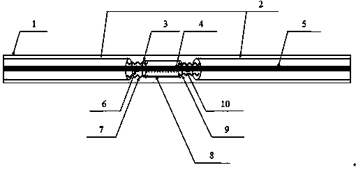
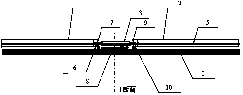
[0025] see Figure 1~Figure 5 , the direct measurement method of geogrid force based on fiber grating technology, is characterized in that the specific operation steps are as follows: the first step, combined with different specifications and different roughness of the casing, through the structural glue and the casing to the fiber grating Point-type fixation realizes the semi-tight sleeve packaging structure of the fiber grating, and protects the grating while ensuring the coordination of deformation; the second step is to stretch the geogrid (1) and pass a method for measuring The calibration method of the stress parameters of geogrid (1) is obtained, and the direct measurement of the stress parameters is realized.

Embodiment 2

[0027] This embodiment is basically the same as Embodiment 1, and the special features are as follows:

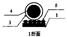
[0028]The semi-tight sleeve packaging structure of the optical fiber grating: the grating section (4) is fixed in point by pasting the front end (6) of the thin sleeve (3) and the rear end (10) of the thin sleeve (3), in order to prevent The grating (5) is damaged due to the displacement of the fine sleeve (3) in actual use, and the contact position (8) between the fine sleeve (3) and the surface of the geogrid (1) is fixed to protect the grating, This fixing method, which prevents the adhesive strip from directly wrapping the grating area (4) and the geogrid (1), can improve the service life of the optical fiber and prevent the structural glue from changing the reinforcement strength of the geogrid. The semi-tight sleeve packaging structure of the fiber grating: the grating in the sensing section is protected by the thin tube (3), ensuring that the grating and the geogrid ...

Embodiment 3

[0030] The problem of direct measurement of the force of the geogrid to be solved by the present invention, the first step is to package the semi-tight package structure of the fiber grating, and the second step is to combine the calibration method for measuring the force parameters of the geogrid, The relationship between the tensile force of the geogrid and the wavelength of the optical fiber is obtained in advance. The semi-tight sleeve encapsulation method in the first step is easy to operate, low in price and good in effect, and is applicable to the deformation and force measurement of geogrids in almost any structure. In the actual use of the calibration method in the second step, only A single calibration of the geogrid of the same type is required to obtain a result relationship curve suitable for the entire geotechnical test or all geogrid force value tests in the entire project. The present invention, which consists of the above two key steps, improves the fixing met...


PUM


Abstract

The invention discloses a direct measurement method of a geogrid force based on the fiber bragg grating technology. The direct measurement method of the geogrid force based on the fiber bragg gratingtechnology comprises two steps of packaging of a fiber bragg grating semi-tight sleeve structure and calibration method of direct measurement of geogrid force parameters, and the specific steps are asfollows: the semi-tight sleeve package structure is realized by combining sleeves with different specifications and roughness, so as to protect the grating while ensuring deformation coordination; the direct measurement of the force parameters is realized through a calibration method for measuring the geogrid force parameters and a system tensile test of the semi-tight sleeve sensing structure geogrid; and roughness treatment is applied to the sleeve of the grating section to realize interface compatibility between the grid surface and the sleeve. On the basis of the direct measurement of thegeogrid force, the invention improves the service life of the optical fiber, prevents the structural adhesive from changing the strength of the grid, improves the tightly occlusive interface compatibility between the sleeve and the geogrid surface, and ensures the coordinated deformation of sleeve and geogrid; and the direct measurement method of the geogrid force based on the fiber bragg gratingtechnology is easy to operate, low in cost and convenient for popularization and use.

Description

technical field [0001] The invention relates to the fields of civil engineering monitoring, water conservancy, transportation, electric power, etc., and in particular to a method for direct measurement of geogrid stress based on fiber grating technology, including a semi-autonomous method for geogrid deformation and force measurement in reinforced soil. A design method for a tight-buffered fiber grating package, and a calibration method for direct force measurement of geogrids. Background technique [0002] In recent years, geogrids have been widely used in geotechnical engineering to reinforce soil, especially in traffic engineering and civil engineering. With the development of polymer materials, geogrid, as a new type of reinforcement material, has been vigorously applied and promoted in the field of civil engineering, and at the same time promotes the continuous improvement of the entire geosynthetics system. [0003] Scholars at home and abroad have conducted a lot of ...

Claims


Application Information

Patent Timeline
IPC IPC(8): G01L1/24
CPCG01L1/242G01L1/247
Inventor 刘倩萁张孟喜韩佳尧张涛涛金琦
Owner SHANGHAI UNIV
Why Eureka
Try Eureka