Injection locking millimeter wave frequency divider based on self-oscillation optical frequency comb and frequency division method thereof

An optical frequency comb, injection locking technology, applied in the field of microwave photonics, can solve the problems of difficult frequency divider, limited bandwidth, difficult high-order nonlinear effects, etc., to achieve large frequency division coefficient, low phase noise, and improved phase Effects of Noise Performance

Active Publication Date: 2019-07-19
PEKING UNIV
View PDF10 Cites 17 Cited by
  • Summary
  • Abstract
  • Description
  • Claims
  • Application Information

AI Technical Summary

Problems solved by technology

[0007] The traditional injection-locked frequency divider based on the LC oscillator is difficult to achieve a frequency divider with a large frequency division ratio in the high frequency range; although the traditional digital frequency divider can achieve a large frequency division ratio and fractional frequency division, but The bandwidth is limited, the operating frequency is usually a few GHz, and it is difficult to work in a higher frequency range; the frequency divider based on the nonlinear effect of the electro-optical modulator and photodetector in the optoelectronic hybrid oscillator, due to the high-order nonlinear effect It is more difficult, so it is also difficult to achieve a frequency divider with a large frequency division ratio

Method used


Image

  • Injection locking millimeter wave frequency divider based on self-oscillation optical frequency comb and frequency division method thereof
  • Injection locking millimeter wave frequency divider based on self-oscillation optical frequency comb and frequency division method thereof
  • Injection locking millimeter wave frequency divider based on self-oscillation optical frequency comb and frequency division method thereof

Examples


Embodiment Construction

[0027] The solutions of the present invention will be further described in detail below in conjunction with the accompanying drawings.

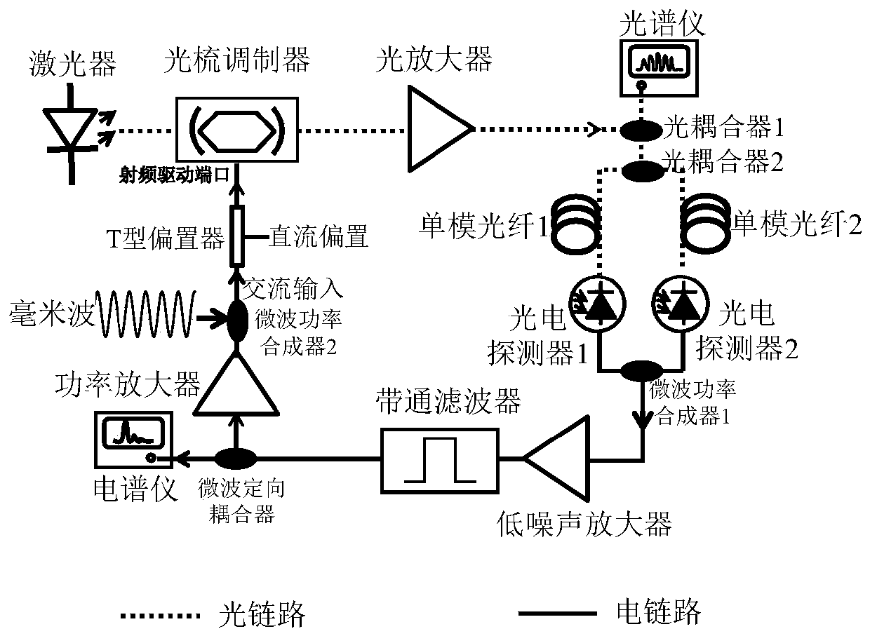
[0028] The scheme principle of the present invention is as image 3 shown. The entire structure is composed of optical links and electrical links, forming a closed loop. The stable high-power laser outputs continuous seed light and injects it into the optical comb modulator. The optical comb modulator is a product of the Japanese company OptoComb. The model is OptoComb WTEC-01-25. It is a lithium niobate phase modulator placed It is formed in the Fabry-Perot cavity, and the Fabry-Perot cavity is realized by coating the two end faces of the lithium niobate modulator with a high reflection film. Due to the large insertion loss of the optical comb modulator, the output optical signal is amplified by the erbium-doped fiber amplifier, and the amplified optical signal is sent to the 5:95 optical coupler 1, and 5% of the optical signal is used to ...


PUM


Abstract

The invention discloses an injection locking millimeter wave frequency divider based on a self-oscillation optical frequency comb and a frequency division method of the injection locking millimeter wave frequency divider. The frequency divider comprises a photoelectric hybrid oscillator, an optical comb modulator is arranged in an optical link of the photoelectric hybrid oscillator, and a band-pass filter is arranged in an electric link of the photoelectric hybrid oscillator; a millimeter wave signal to be subjected to frequency division is injected into the photoelectric hybrid oscillator; wherein the central frequency of the millimeter wave signal is an integral multiple of the central frequency of the band-pass filter, the optical frequency comb sideband generated by the photoelectric hybrid oscillator and the modulation sideband of the signal to be converted output a fundamental frequency signal in a beat frequency mode, and the fundamental frequency signal is located within the locking bandwidth range of the photoelectric hybrid oscillator. When a super-harmonic signal is injected into the oscillation loop and locked, the frequency division function of the injected millimeterwave signal can be realized, and the frequency divider has the characteristics of wide band, low phase noise and large frequency division ratio.

Description

technical field [0001] The invention relates to a frequency divider suitable for millimeter waves and a frequency division method thereof. It is realized by a self-oscillating optical frequency comb based on an optoelectronic hybrid oscillator structure. The optical frequency comb can generate a fundamental frequency oscillating signal with broadband and low phase noise performance through a clock extraction circuit. When a superharmonic signal is injected into the oscillating loop and locked, the frequency division function of the injected millimeter wave signal can be realized. The frequency divider has the characteristics of broadband, low phase noise and large frequency division ratio, and belongs to the field of microwave photonics. Background technique [0002] The frequency divider is a key device in microwave and millimeter wave circuits, and its function is to achieve integer or fractional frequency division of the frequency of the input signal. Microwave and mill...

Claims


Application Information

Patent Timeline
Patent Type & Authority Applications(China)
IPC IPC(8): H03L7/18G02B27/00
CPCG02B27/00H03L7/18
Inventor 徐永驰彭焕发解晓鹏郭锐杜华阳胡康陈章渊
Owner PEKING UNIV
Why Eureka
Try Eureka