
Fuel oil catalysis system with catalytic converter and assembling method thereof

A catalytic system and catalytic converter technology, which is applied in the field of fuel catalytic converters, can solve the problems of large influence of ambient temperature and catalytic effect, and achieve the effect of high safety factor and stable oil pressure

Inactive Publication Date: 2019-07-23
广州市速马力汽车配件有限公司
View PDF6 Cites 0 Cited by
  • Summary
  • Abstract
  • Description
  • Claims
  • Application Information

AI Technical Summary

Problems solved by technology

[0003] The existing methods for improving automobile exhaust gas and improving combustion efficiency are as follows: The first is to use a thermocatalytic fuel oil energy-saving and emission reducer, by heating the oil temperature to control the temperature of the catalyst, and through the low melting point of the catalyst surface, components with strong migration ability promote carbon Low-temperature combustion of smoke, the other is to activate the combustion of soot through the active oxygen species on the surface of the catalyst, improve the catalytic effect of the catalyst, and achieve fuel energy saving and emission reduction, but this technology is greatly affected by the ambient temperature during use, especially in the north In winter, the temperature is very low, which seriously affects the catalytic effect of the product

Method used


Image

  • Fuel oil catalysis system with catalytic converter and assembling method thereof
  • Fuel oil catalysis system with catalytic converter and assembling method thereof
  • Fuel oil catalysis system with catalytic converter and assembling method thereof

Examples


Embodiment Construction

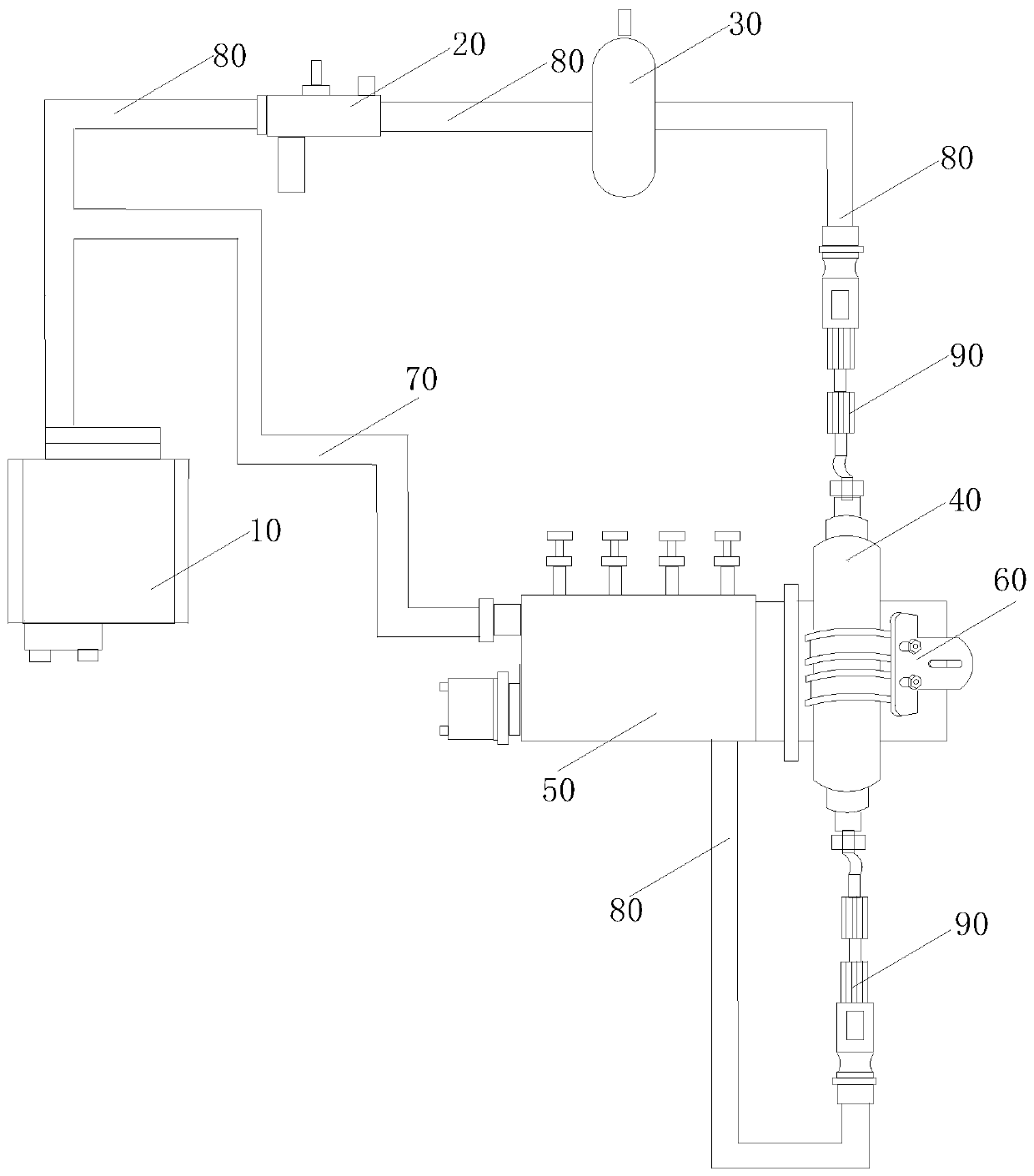
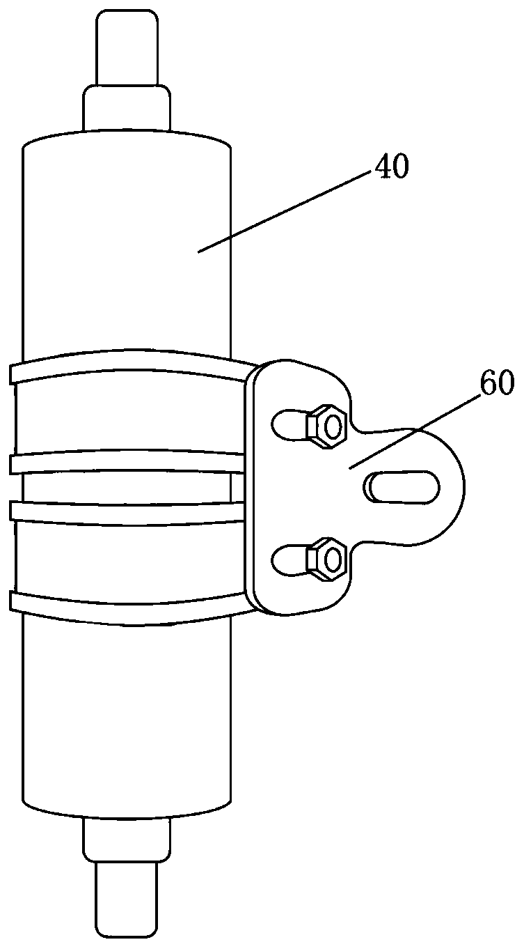
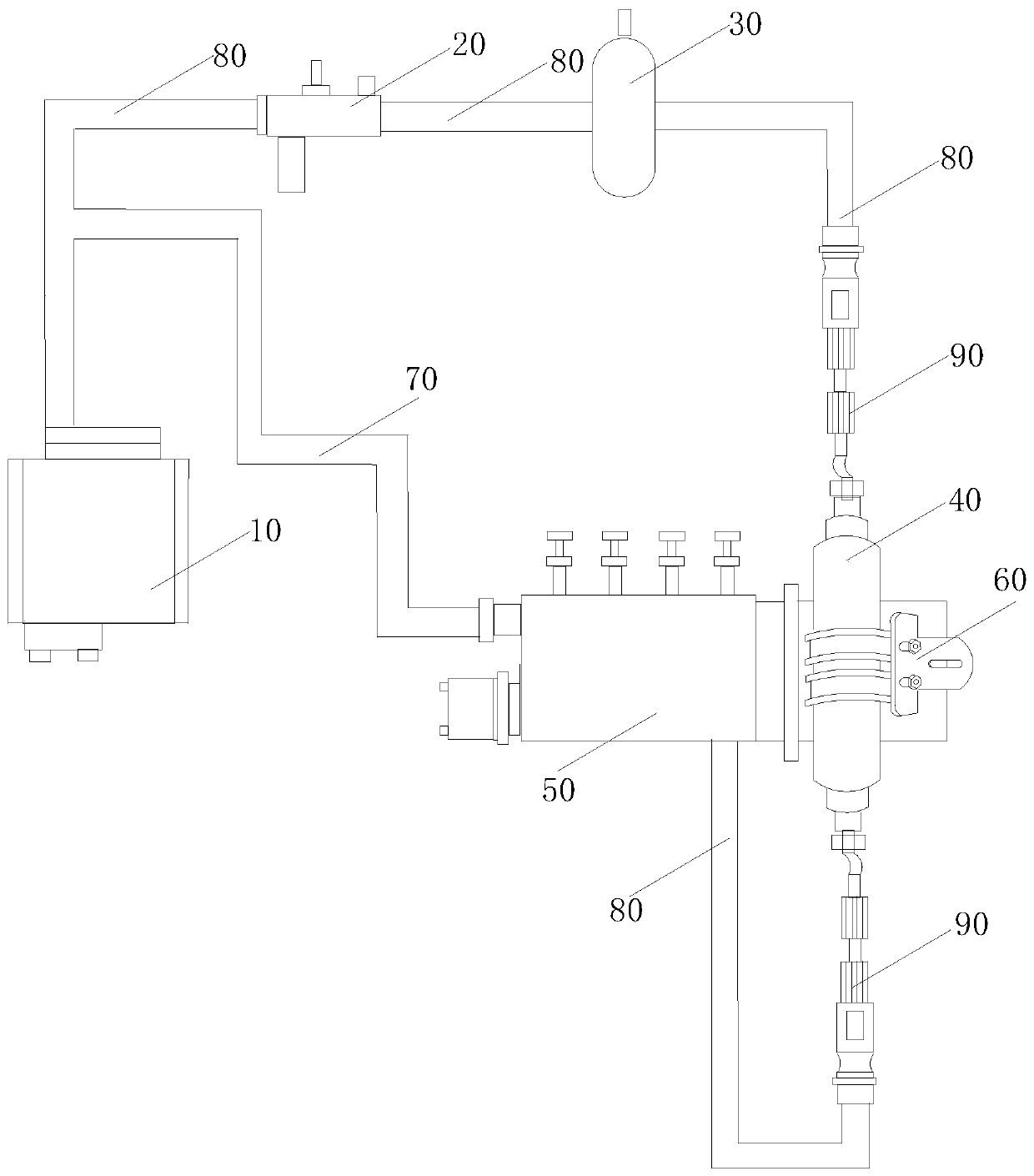
[0022] In this example, refer to figure 1 and figure 2 , a fuel catalytic system with a catalytic converter, including a fuel tank 10 and an engine 50, the fuel tank 10 is connected to the engine 50 through a fuel pipe 80, the oil pipe 80 is equipped with a fuel cut-off port 90, and the fuel cut-off ports 90 are connected There is a fuel catalyst 40, wherein the fuel catalyst 40 is fixedly installed on the engine 50. When the engine 50 starts, the vibration of the engine 50 drives the fuel catalyst 40 to vibrate, so that the oil molecules in the fuel catalyst 40 It is catalyzed into a single oil molecule, which is easy to fully burn; the fuel catalyst 40 is fixedly installed on the engine 50 through a fastening bracket 60. During installation, the fastening bracket 60 is sleeved on the surface of the fuel Screw adjustment is fixed.

[0023] The described fuel catalytic system with catalytic converter also includes a filter 30, the filter 30 is arranged between the fuel tank...


PUM


Abstract

The invention provides a fuel oil catalysis system with a catalytic converter and an assembling method thereof. The fuel oil catalysis system comprises an oil tank and an engine, the oil tank is connected with the engine through an oil pipe, oil breaking openings are formed in the oil pipe, the fuel oil catalytic converter is connected between the oil breaking openings, the fuel oil catalytic converter is fixedly arranged on the engine, when the engine is started, the fuel oil catalytic converter is driven to vibrate through the vibration of the engine, so that oil molecular groups in the fueloil catalytic converter are catalyzed into single oil molecules to be easily combusted sufficiently. According to the fuel oil catalysis system with the catalytic converter and the assembling methodthereof, the fuel oil catalytic converter is arranged on the engine, so that the oil molecules in the fuel oil catalytic converter are rubbed through the thermo-vibration catalytic effect by utilizingthe vibration of the engine, so that the density of the oil molecules in the fuel oil catalytic converter is reduced, and then the oil molecules are sufficiently combusted.

Description

technical field [0001] The invention relates to the technical field of fuel catalytic converters, in particular to a catalytic fuel oil catalytic system with catalytic converters and an assembly method thereof which improves combustion efficiency by catalyzing fuel oil before combustion. Background technique [0002] Automobile exhaust gas pollution is environmental pollution caused by exhaust gas emitted by automobiles. The main pollutants are hydrocarbons, nitrogen oxides, carbon monoxide, sulfur dioxide, lead-containing compounds, etc., which can cause photochemical smog, etc. Therefore, the treatment of automobile exhaust gas around the world We attach great importance to it, and the most accessible thing for people is to continuously improve the standards of automobile exhaust emissions. [0003] The existing methods for improving automobile exhaust gas and improving combustion efficiency are as follows: The first is to use a thermocatalytic fuel oil energy-saving and e...

Claims


Application Information

Patent Timeline
Patent Type & Authority Applications(China)
IPC IPC(8): F02M27/02F02M37/00
CPCF02M27/02F02M37/0047Y02T10/12
Inventor 吕亦瑜
Owner 广州市速马力汽车配件有限公司
Learn More