Drilling device for construction metal plates

A technology for sheet metal and drilling equipment, applied in metal processing equipment, drilling/drilling equipment, boring/drilling, etc., can solve the problem of decreased drilling accuracy, affecting drilling accuracy, and drill pipe grinding and cutting deviation and other problems, to achieve the effect of preventing debris from splashing, facilitating subsequent processing, and preventing slipping

Inactive Publication Date: 2019-07-26
吕谋
View PDF7 Cites 9 Cited by
  • Summary
  • Abstract
  • Description
  • Claims
  • Application Information

AI Technical Summary

Problems solved by technology

[0003] Sheet metal is a very common building material. At present, the drilling equipment for sheet metal on the market is equipped with clamping components to fix the sheet, mainly for positioning the sheet and avoiding the deviation of the sheet and affecting the dril

Method used


Image

  • Drilling device for construction metal plates
  • Drilling device for construction metal plates
  • Drilling device for construction metal plates

Examples


Example Embodiment

[0022] Example 1

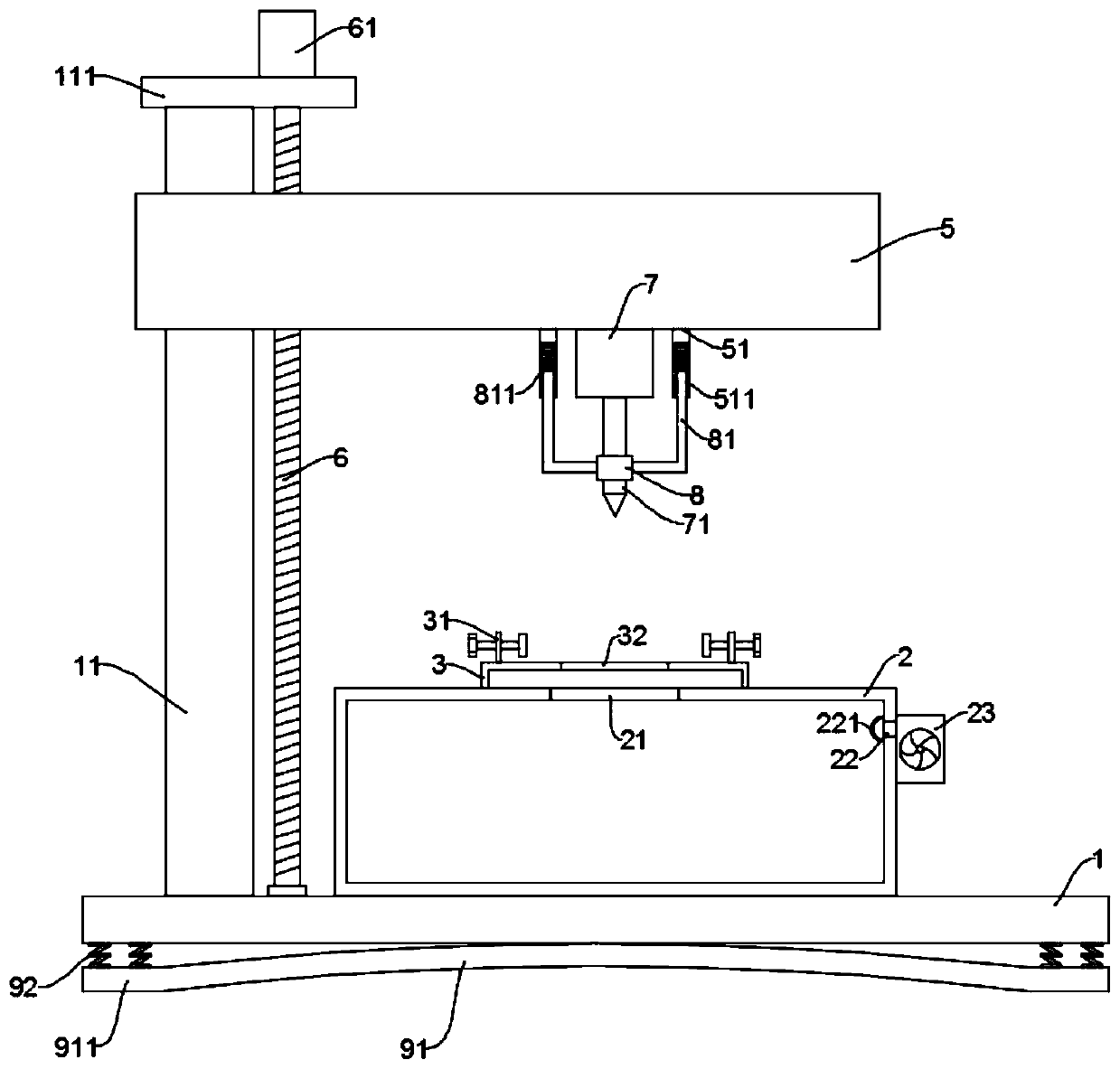
[0023] See Figure 1~2 In the embodiment of the present invention, a drilling equipment for building sheet metal includes a base 1, a workbench 2, and a movable frame 5; the top of the base 1 is fixed with a guide column 11, and the movable frame 5 is slidably installed on the guide column On 11, it is used to limit the movement direction of the movable frame 5. A top plate 111 is fixed on the top of the guide column 11, and a screw rod 6 is rotatably connected between the top plate 111 and the base 1. The screw rod 6 is connected to the movable frame 5 through threaded fit. A feed motor 61 that drives the screw 6 to rotate is installed on the top plate 111. During operation, the feed motor 61 drives the screw 6 to rotate, thereby driving the moving frame 5 to rise and fall to complete the drilling and feeding work. Transmission can make the lifting of the mobile frame 5 more stable;

[0024] A storage table 3 is fixed on the top of the workbench 2, and a clampi...

Example Embodiment

[0030] Example 2

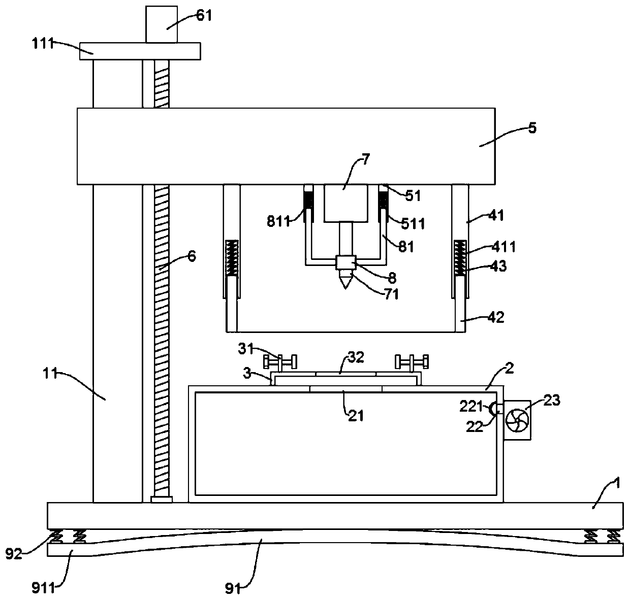
[0031] See Figure 3~4 The embodiment of the present invention is optimized on the basis of embodiment 1, mainly to solve the problem of debris splashing during the drilling process, specifically:

[0032] The bottom of the movable frame 5 is also fixed with a sealing cover which covers the table 3; the sealing cover includes a fixed cover 41 and a movable cover 42, wherein the fixed cover 41 is connected to the mobile frame 5, The bottom of the fixed cover 41 is provided with an annular slot 411. The upper part of the movable cover 42 extends into the slot 411 and is connected to the slot 411 through a connecting spring 43. When the connecting spring 43 is in a normal state, the movable cover The lower end surface of the body 42 is lower than the drill rod 71. During the drilling process, the sealing cover will form a closed space with the movable frame 5 and the worktable 2 to effectively prevent the debris from splashing. The plug-in fixed cover 41 and movabl...


PUM


Abstract

The invention discloses a drilling device for construction metal plates, and relates to the field of machining. By adoption of the drilling device for the construction metal plates, the problem that atraditional drilling device only positions plates, and consequentially, the drilling precision cannot be ensured is mainly solved. The drilling device comprises a base, a workbench and a movable frame, wherein a rotary motor is mounted at the position, right facing a storage table, of the bottom of the movable frame, and a shaft stretching end of the rotary motor is connected with a drill stem; the periphery of a stem body of the drill stem is slidably sleeved with a positioning sleeve, and L-shaped rods are symmetrically fixed to the two sides of the positioning sleeve; and connecting columns matched with the L-shaped rods are fixed to the bottom of the movable frame and are provided with insertion grooves which are open downwards, and vertical rod bodies of the L-shaped rods are slidably clamped in the insertion grooves. According to the drilling device for the construction metal plates, the positioning sleeve is arranged to position the drill stem when the drill stem makes contactwith the plates, so that slipping of the drill stem is prevented, and the drilling precision is ensured; and meanwhile, the positioning sleeve moves synchronously when the drill stem is fed, so that feeding of the drill stem is avoided.

Description

Technical field [0001] The invention relates to the field of building materials processing, in particular to a drilling equipment for building metal plates. Background technique [0002] Building materials is a general term for materials used in civil engineering and construction engineering. Can be divided into structural materials, decorative materials and some special materials. Structural materials include wood, bamboo, stone, cement, concrete, metal, bricks, ceramics, glass, engineering plastics, composite materials, etc. [0003] Sheet metal is a very common building material. At present, the drilling equipment for sheet metal on the market is equipped with clamping components for fixing the sheet, mainly for positioning the sheet and avoiding the deviation of the sheet and affecting the drilling. However, in actual work, due to the smooth surface of the plate, the drill rod is prone to deviation during grinding, and the deviation of the drill rod will also cause the drilli...

Claims


Application Information

Patent Timeline
IPC IPC(8): B23B41/00B23B47/20B23Q3/06B23Q11/00B23Q11/08
CPCB23B41/00B23Q3/06B23Q5/28B23Q11/0032B23Q11/005B23Q11/08
Inventor 吕谋
Owner 吕谋
Why Eureka
Try Eureka