Picosecond laser galvanometer equipment with same light source and double galvanometers
What is Al technical title?
Al technical title is built by PatSnap Al team. It summarizes the technical point description of the patent document.
A picosecond laser and dual galvanometer technology, applied in the field of laser processing equipment and picosecond laser galvanometer precision equipment, can solve the problems of low processing efficiency, high laser power, and difficult to precisely control the cutting size, so as to ensure product quality. Consistency, good process adaptability, remarkable practical effect
Pending Publication Date: 2019-07-26
WUHAN GSTAR TECH CO LTD
View PDF0 Cites 2 Cited by
Summary
Abstract
Description
Claims
Application Information
AI Technical Summary
This helps you quickly interpret patents by identifying the three key elements:
Problems solved by technology
Method used
Benefits of technology
Problems solved by technology
(1) The laser power required by the fusion cutting method is high, the cutting size is difficult to control precisely, the cutting surface is rough, and the processing quality needs to be improved
(2) The stress cutting method cannot solve the problem of curved surface and special-shaped cutting
(3) The cutting speed of laser ablation (ablation) is relatively slow, and the processing efficiency is not high
The existing laser equipment for cutting glass has a single structure of marble base, which cannot meet the requirements of strength and stability; at the same time, the galvanometer system is usually installed on a moving Y or Z-axis motion platform, which cannot fully meet the needs of glass cutting. High-precision requirements in terms of contour, cutting accuracy, processing efficiency, cutting cracks, cutting strength, process adaptability, etc., have great limitations
Method used
Image
Click on the blue label to locate the original text in one second.
Reading with bidirectional positioning of images and text.
Examples
Embodiment Construction
[0026] Below in conjunction with accompanying drawing and specific embodiment, further illustrate the present invention, should be understood that these embodiments are only for illustrating the present invention and are not intended to limit the scope of the present invention, after having read the present invention, those skilled in the art will understand various aspects of the present invention Modifications in equivalent forms all fall within the scope defined by the appended claims of this application.
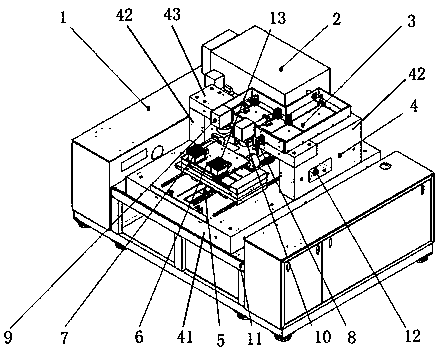
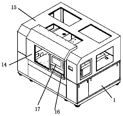
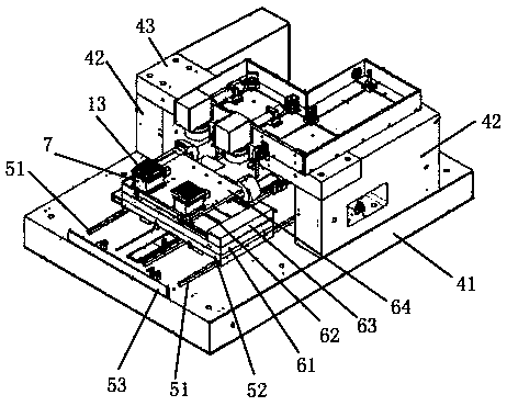
[0027] Such as figure 1 , figure 2 , image 3 As shown, a picosecond laser galvanometer device with double vibrating mirrors with the same light source includes a frame 11, a marble base 4, a power distribution cabinet 1, a control system 16, a display system 17, a door control mechanism 14, an outer cover assembly 15, a vacuum Generator 12, vacuum adsorption system 13, X-axis moving system 6, Y-axis moving system 5, Z-axis moving system 7, also includes: laser 2, opt...
PUM
Abstract
The invention discloses picosecond laser galvanometer equipment with a same light source and double galvanometers. The equipment comprises a rack, a marble base, a power distribution cabinet, a control system, a display system, a door control mechanism, an outer cover assembly, a vacuum generator, a vacuum adsorption system, an XYZ axis moving system, a laser device, an optical path integration, the galvanometers and a telecentric variable focusing lens. The marble base is composed of a base, a vertical base and a top base, and sequentially provided with a Y-axis moving system, an X-axis moving system, two Z-axis moving systems and a vacuum adsorption system, the telecentric variable focusing lens and the galvanometers are coaxially mounted, the distances between the axes are consistent, and the laser device is the picosecond grade laser generation device. Product quality consistency is ensured by adopting the same light source, the marble base is of an integrated structure, high-precision curve cutting, punching, grooving and edging are realized by matching the galvanometers with the telecentric variable focusing lens, processing precision, product quality and production efficiency are improved, the process adaptability is good, and the practical effect is remarkable.
Description
technical field [0001] The invention relates to a laser processing equipment, in particular to a picosecond laser vibrating mirror precision equipment, and mainly relates to the technical field of precision cutting equipment for cutting glass. Background technique [0002] At present, glass products are used in all aspects of daily life and are in great demand. Corresponding cutting of different glass materials also has a large market demand. [0003] With the development of technology, the cutting methods of glass are also constantly updated. At present, laser cutting is the main method, which has many advantages compared with traditional mechanical cutting methods, mainly including fusion cutting, stress cutting (crack control method), There are several cutting methods such as ablative (ablation) cutting. (1) The laser power required by the fusion cutting method is high, the cutting size is difficult to control precisely, the cutting surface is rough, and the processing ...
Claims
Application Information
Patent Timeline
Application Date:The date an application was filed.
Publication Date:The date a patent or application was officially published.
First Publication Date:The earliest publication date of a patent with the same application number.
Issue Date:Publication date of the patent grant document.
PCT Entry Date:The Entry date of PCT National Phase.
Estimated Expiry Date:The statutory expiry date of a patent right according to the Patent Law, and it is the longest term of protection that the patent right can achieve without the termination of the patent right due to other reasons(Term extension factor has been taken into account ).
Invalid Date:Actual expiry date is based on effective date or publication date of legal transaction data of invalid patent.