Rotary derusting machine
A derusting machine, rotary technology, applied in the direction of grinding frame, grinding machine parts, grinding machines, etc., can solve the problems of excessive loss of raw materials, heavy workload, unstable operation of equipment, etc., to reduce the failure rate of equipment , prolong the service life and improve the effect of rust removal efficiency
- Summary
- Abstract
- Description
- Claims
- Application Information
AI Technical Summary
Problems solved by technology
Method used
Image
Examples
Embodiment 1
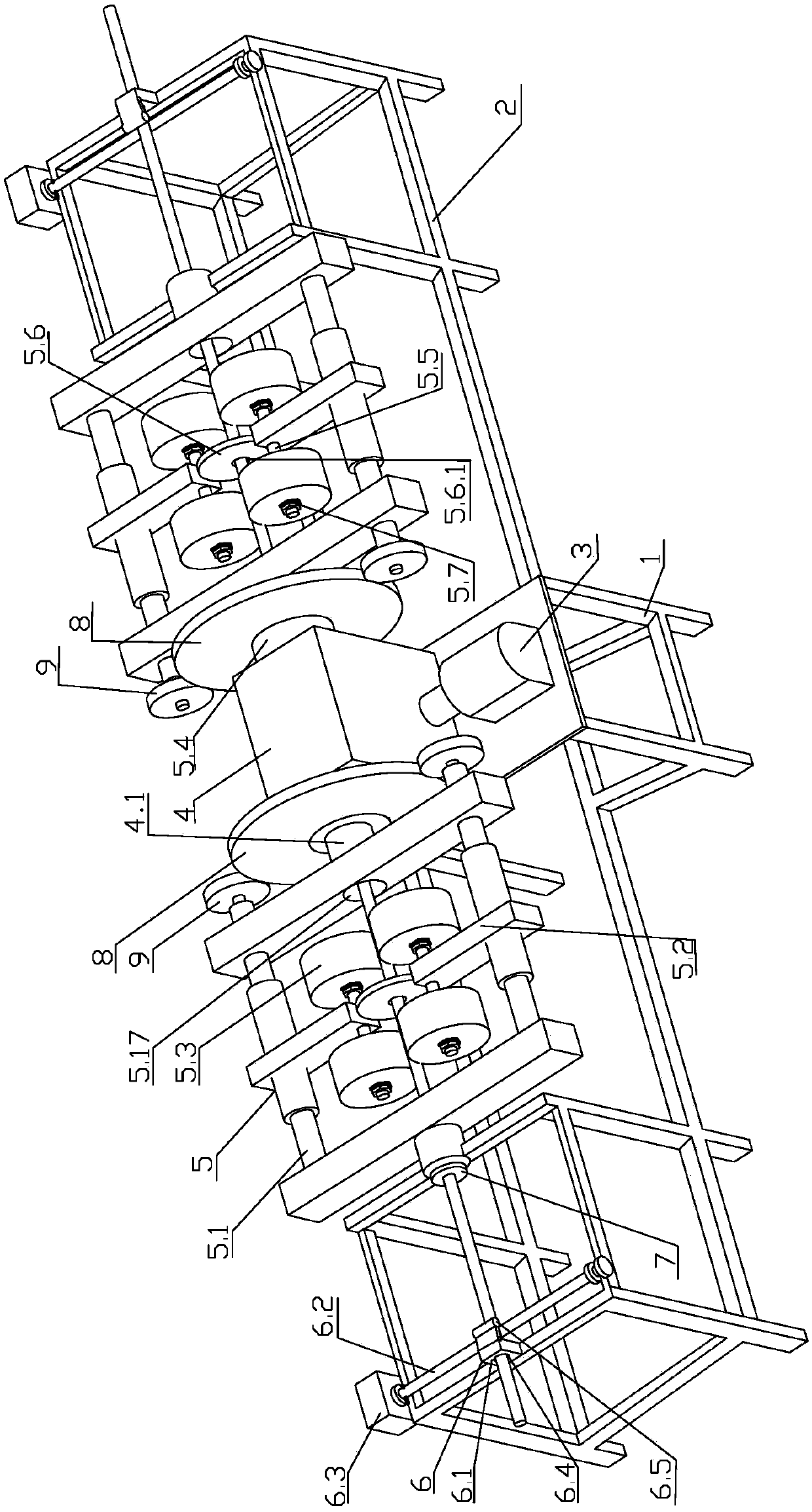
[0030] Embodiment 1: as figure 1 As shown, the rotary derusting machine includes a middle drive support frame 1, an end support frame 2, a drive motor 3, a primary gearbox 4 and a rotary rust removal mechanism 5,
[0031] An end support frame 2 is respectively arranged on both sides of the middle part drive support frame 1, and the middle part drive support frame 1 and the end support frames 2 on both sides are fixedly connected as one by a connecting beam; at each end support frame 2 A conveying device 6 is arranged on the top, and the conveying device 6 includes a conveying frame 6.1, a conveying shaft 6.2 and a conveying motor 6.3, and the conveying frame 6.1 is provided with a perforation 6.4 corresponding to the central hole of the primary output shaft 4.1; in the perforation 6.4 The conveyor frame 6.1 on one side is rotated and provided with a conveyor shaft 6.2 whose axis is perpendicular to the primary output shaft 4.1, and the conveyor motor 6.3 is connected to the co...
Embodiment 2
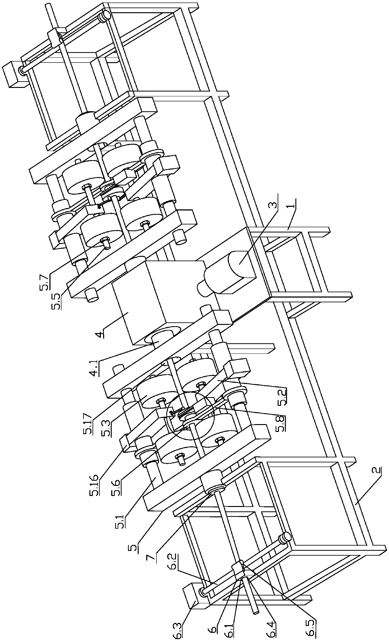
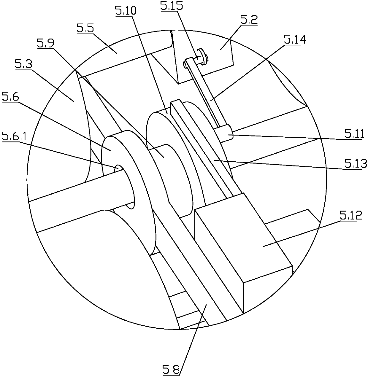
[0043] Embodiment 2: as figure 2 and image 3 As shown, the rotary derusting machine includes a middle drive support frame 1, an end support frame 2, a drive motor 3, a primary gearbox 4 and a rotary rust removal mechanism 5,
[0044] An end support frame 2 is respectively arranged on both sides of the middle drive support frame 1, and the middle drive support frame 1 and the end support frames 2 on both sides are fixedly connected as a whole through a connecting beam; fixed on the top of the middle drive support frame 1 There is a drive motor 3 and a primary gearbox 4, the output shaft of the drive motor 3 is connected to the input shaft of the primary gearbox 4, and the drive motor 3 drives the primary gearbox 4 to rotate; between the primary gearbox 4 and the ends of both sides On the opposite side walls of the support frame 2 are respectively coaxially arranged a first-level output shaft 4.1 arranged horizontally, and the two first-level output shafts 4.1 can rotate sync...
Embodiment 3
[0056] Embodiment 3: as Figure 6 and Figure 7 As shown, the rotary derusting machine includes a middle drive support frame 1, an end support frame 2, a drive motor 3, a primary gearbox 4 and a rotary rust removal mechanism 5,
[0057]An end support frame 2 is respectively arranged on both sides of the middle part drive support frame 1, and the middle part drive support frame 1 and the end support frames 2 on both sides are fixedly connected as one by a connecting beam; at each end support frame 2 A conveying device 6 is provided on the top, and the conveying device 6 includes a conveying frame 6.1, a conveying shaft 6.2 and a conveying motor 6.3, and the conveying frame 6.1 is provided with a perforation 6.4 corresponding to the center hole of the primary output shaft 4.1; One side of 6.1 rotates and is provided with a roller 6.5 and a conveying shaft 6.2 whose axis is perpendicular to the primary output shaft 4.1, and the roller 6.5 and conveying shaft 6.2 are respectively...
PUM
 Abstract
Description
Claims
Application Information
 - R&D
- Intellectual Property
- Life Sciences
- Materials
- Tech Scout
- Unparalleled Data Quality
- Higher Quality Content
- 60% Fewer Hallucinations
Browse by: Latest US Patents, China's latest patents, Technical Efficacy Thesaurus, Application Domain, Technology Topic, Popular Technical Reports.
© 2025 PatSnap. All rights reserved.Legal|Privacy policy|Modern Slavery Act Transparency Statement|Sitemap|About US| Contact US: help@patsnap.com


